Spiral extrusion separator

A technology of screw extrusion and separator, applied in the direction of presses, manufacturing tools, etc., can solve the problems of complex opening of the cover plate, easy accumulation of slag near the cover plate, etc., and achieve simple structure, simple and fast improved structure The effect of discharge

Inactive Publication Date: 2019-06-07
NANJING TAOTESI SOFTWARE TECH CO LTD
View PDF0 Cites 2 Cited by
  • Summary
  • Abstract
  • Description
  • Claims
  • Application Information

AI Technical Summary

Problems solved by technology

[0003] The purpose of the present invention is to provide a screw extrusion separator to solve the problems of the complex opening method of the cover plate and the easy accumulation of slag near the cover plate in the above background technology.

Method used


Image

  • Spiral extrusion separator
  • Spiral extrusion separator
  • Spiral extrusion separator

Examples


Embodiment 1

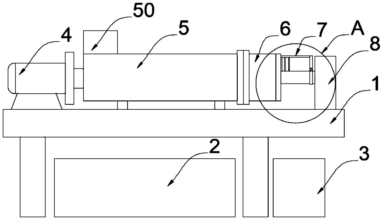
[0023] A screw extrusion separator, such as figure 1 with figure 2 As shown, including the support 1, the bottom of the support 1 is provided with a material receiving trough 2, one side of the material receiving trough 2 is provided with a discharge frame 3, the upper end of the support 1 is equipped with a motor 4, and one side of the motor 4 is equipped with a screw The casing 5, one side of the spiral casing 5 is fixed with a discharge area 6 by bolts, one side of the discharge area 6 is provided with a lever 7, and one side of the lever 7 is welded with a fixed block on the bracket 1 8.

[0024] Specifically, the discharge tray 60, the material shifting rod 7 and the thin rod 72, the fixing rod 70 and the fixing ring 701 of this embodiment are all made of plastic molds, and all use PA plastic raw materials, that is, nylon, which has a high Mechanical strength, heat resistance, and wear resistance make their structures stable, durable, rust-free, and easy to replace.

...

Embodiment 2

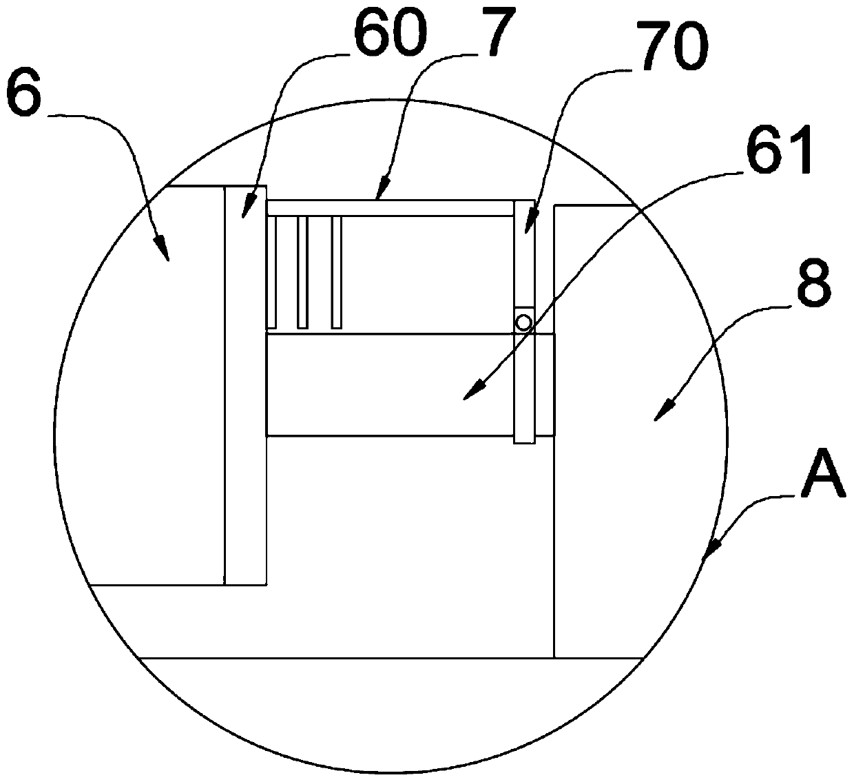
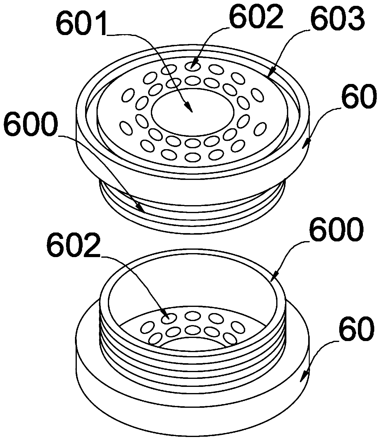
[0027] In the specific implementation, because the opening method of the original structure cover plate on the side of the discharge area is too cumbersome and takes up space, and the extruded slag has a high adhesiveness, in order to simplify the original structure at the end of the discharge area, the material The slag is not easy to accumulate, and the inventor improves the material shifting rod 7, as a preferred embodiment, as image 3 , Figure 4 with Figure 5 As shown, one end of the driving rod 7 is fixed with a fixed rod 70 by a bolt, the other end of the driving rod 7 is connected with a roller 71, and one side of the driving rod 7 is equidistantly provided with some thin rods 72, and one part of the fixed rod 70 The side is provided with a fixing hole 700, the bottom end of the fixing rod 70 is provided with a fixing ring 701, the bottom end of the fixing ring 701 is provided with a notch 702, one side of the fixing ring 701 is connected with a snap ring 703, and t...


PUM


Abstract

The invention relates to the technical field of spiral separators, in particular to a spiral extrusion separator. The separator comprises a support, wherein a material receiving groove is formed belowthe support, a material discharging frame is arranged on one side of the material receiving groove, a motor is installed at one end above the support, one side of the motor is provided with a spiralcasing, one side of the spiral casing is fixedly provided with a discharging area through bolts, one side of the discharging area is provided with a material stirring rod, a fixing block is welded onone side of the material stirring rod and located on the support, a fixing rod is fixed at one end of the material stirring rod through bolts, and a plurality of thin rods are arranged at equal intervals on one side of the material shifting rod. According to the separator, an extruded material slag is discharged through a discharging hole in a discharging plate, the structure is simple, the spaceis saved, installation is convenient, and discharging of the material slag is facilitated; and when the fixing rod rotates with a rotating shaft, so that the thin rods can be driven to shift down accumulated materials on the discharging plate, so that the materials fall into the discharging frame, the structure is simple, the material slag cannot be accumulated, rapid discharging is achieved, andthe phenomenon that pressure in the separator is too large is avoided.

Description

technical field [0001] The invention relates to the technical field of screw separators, in particular to a screw extrusion separator. Background technique [0002] For poultry and livestock manure, the liquid separated by the screw extrusion separator can produce biogas after anaerobic treatment, which can be used as fuel, power generation or as foliar fertilizer after pressure filtration, and can also be pumped to the greenhouse as a feeder for plants. nutrient. The separated solid matter is almost odorless, easy to transport, and can be directly used as organic fertilizer. great economic benefits. However, the discharge area of ​​the machine is hinged with a cover plate and opened through the linkage of the pull rod. In view of this, we propose a screw extrusion separator. Contents of the invention [0003] The purpose of the present invention is to provide a screw extrusion separator to solve the problems in the above-mentioned background art that the opening of th...

Claims


Application Information

Patent Timeline
Patent Type & Authority Applications(China)
IPC IPC(8): B30B9/12B30B15/32B30B15/00
Inventor 赵卫政黄乃佳许如安
Owner NANJING TAOTESI SOFTWARE TECH CO LTD
Why Eureka
Try Eureka