Electromechanical servo steering system having a spring-loaded bearing arrangement

A technology of steering system and electromechanical servo, which is applied in the direction of electric steering mechanism, portable lifting device, rigid support of bearing components, etc., and can solve the problems of increased tooth surface clearance of coupling, different thermal expansion, tolerance, etc.

Active Publication Date: 2019-06-04
THYSSENKRUPP PRESTA AG +1
View PDF7 Cites 0 Cited by
  • Summary
  • Abstract
  • Description
  • Claims
  • Application Information

AI Technical Summary

Problems solved by technology

This configuration has been shown to be disadvantageous because the coupling is subjected to greater loads, as a result of which the coupling wears out more quickly over time and increases the tooth flank clearance with corresponding vibration noises
[0005] Furthermore, it is known to construct bearings with a large amount of play so that the required pivotability is possible
However, the problem with this approach is that differential thermal expansion occurs due to large component tolerances

Method used


Image

  • Electromechanical servo steering system having a spring-loaded bearing arrangement
  • Electromechanical servo steering system having a spring-loaded bearing arrangement
  • Electromechanical servo steering system having a spring-loaded bearing arrangement

Examples


Embodiment Construction

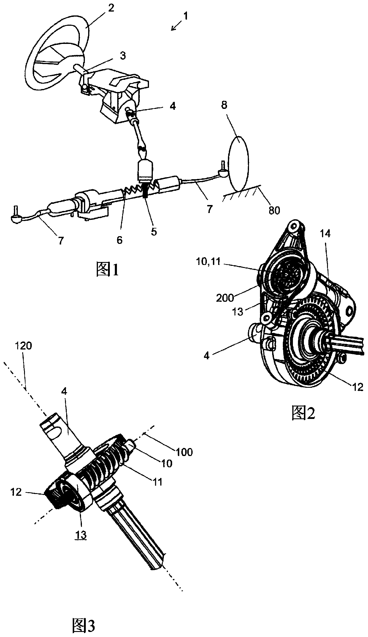
[0034] exist figure 1 An electromechanical motor vehicle steering system 1 with a steering wheel 2 coupled to an upper steering shaft 3 and a lower steering shaft 4 in a rotationally fixed manner (drehfest) is schematically illustrated in FIG. The upper steering shaft 3 is functionally connected to the lower steering shaft 4 via torsion bars. The lower steering shaft 4 is connected to a pinion 5 in a rotationally fixed manner. The pinion 5 meshes with the toothed section of the toothed rack 6 in the usual manner. The rack 6 is mounted in the steering housing displaceably in the direction of its longitudinal axis. The toothed rack 6 is connected at its free end to the tie rod 7 via a ball joint, not shown. The tie rods 7 are themselves connected in the usual manner via journals to one steered wheel 8 of the motor vehicle, respectively. Rotation of the steering wheel 2 via the connection of the steering shafts 3 , 4 and the pinion 5 causes a longitudinal displacement of the ...


PUM


Abstract

The invention relates to an electromechanical servo steering system having an electric servomotor with a motor shaft, which drives a shaft (10) meshing with a helical gear (12), wherein the shaft (10)is arranged in a gearbox (14) and the end of the shaft in the vicinity of the motor is mounted in a bearing arrangement (13) so as to be rotatable about an axis of rotation (100), and said shaft is mounted in the gearbox (14) so as to be pivotable about a pivot axis (22) lying perpendicular to the axis of rotation (100), and at least one spring element (23) is provided which axially pre-stressesa bearing element (19), which is pivotable together with the shaft (10) about the pivot axis (22), of the bearing arrangement (13) spring elastically against a bearing element (21), which is arrangedin a fixed position in the gearbox (14), of the bearing arrangement (13), wherein precisely two spring elements (23) are provided which are arranged opposite each other in the circumferential direction of the bearing arrangement (13).

Description

technical field [0001] The invention relates to an electromechanical servo steering system having the features of the preamble of claim 1 . Background technique [0002] In an electromechanical servo steering system, an electric motor generates a torque which is transmitted to a transmission and superimposed in the transmission with a steering torque provided by the driver. [0003] A typical electromechanical servo steering system includes an electric servo motor that will drive a worm shaft that engages a worm gear disposed on the steering shaft, wherein the worm gear is operatively connected to the input shaft of the steering transmission, and wherein , the worm shaft and the steering shaft are rotatably installed in the combined transmission housing. The worm shaft is connected to the motor shaft of the electric servo motor via a coupling. [0004] DE 10 2008 001 878 A1 discloses a pivot bearing for a worm gear drive, wherein the worm wheel is mounted by means of a car...

Claims


Application Information

Patent Timeline
IPC IPC(8): B62D5/04F16H55/24F16C35/077
CPCB62D5/0409F16C35/077F16H55/24F16C2361/61F16C2326/24F16C23/084F16C25/083F16C19/16F16C2380/26F16H1/16F16H57/022F16H57/039F16H57/12F16H2057/0213F16H2057/0222F16H2057/127
Inventor 迈克尔·布拉塞尔乌尔里希·施莱格尔马里奥·达伦巴赫迈克尔·多纳
Owner THYSSENKRUPP PRESTA AG
Why Eureka
Try Eureka