
WEB-based lamplight control system

A lighting control and dimming control technology, applied in the field of lighting control, can solve the problems of inconvenient adjustment, prominent cluster control, and inability to apply lighting control, and achieve the effect of avoiding inconvenient adjustment, strong scalability and adaptability

Inactive Publication Date: 2019-06-04
刘明远
View PDF10 Cites 2 Cited by
  • Summary
  • Abstract
  • Description
  • Claims
  • Application Information

AI Technical Summary

Problems solved by technology

For a single lamp, you can use a shading plate or an iris diaphragm to change the amount of light transmitted by the lamp; another method is the electrical control method, that is, using various dimmers to change the operating voltage or current of the lamp to adjust the brightness of the lamp. The luminous intensity of the lamps, these two methods have their own characteristics, the advantage of the first method is that it will not affect the color temperature, but the adjustment is not convenient enough
The second method is simple to operate, and can realize automatic and program-controlled operation. Its disadvantage is that the color temperature and color rendering will change greatly when the luminous intensity is changed.
[0007] (1) The mechanical addition and subtraction method is not convenient to adjust, and the electrical control method changes the luminous intensity while causing a large change in color temperature and color rendering
[0008] (2) With the continuous expansion of the scale of the lighting equipment system, the number of equipment is large and the distribution is wide, leading to the problem of cluster control gradually becoming prominent
At this stage, lighting control does not have strong scalability and adaptability, resulting in lighting control that cannot be applied to various occasions (such as: stage, factory, etc.)

Method used


Image

  • WEB-based lamplight control system
  • WEB-based lamplight control system
  • WEB-based lamplight control system

Examples


Embodiment Construction

[0054] In order to make the object, technical solution and advantages of the present invention more clear, the present invention will be further described in detail below in conjunction with the examples. It should be understood that the specific embodiments described here are only used to explain the present invention, not to limit the present invention.

[0055] The application principle of the present invention will be described in detail below according to the accompanying drawings.

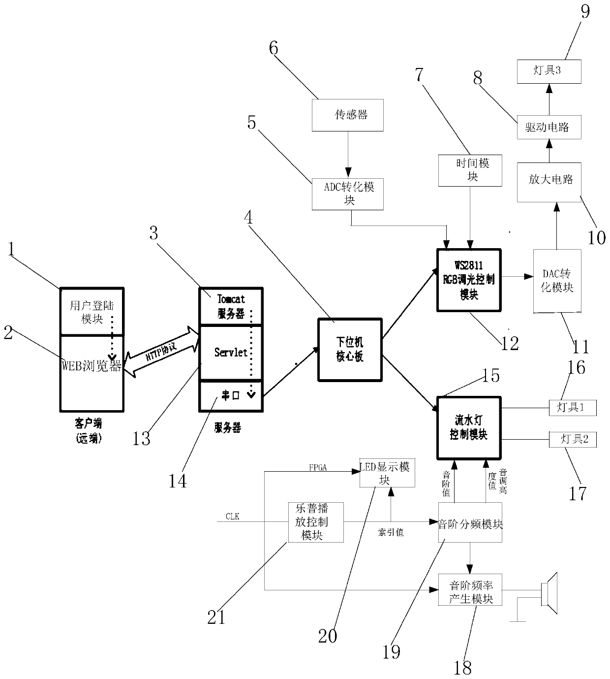
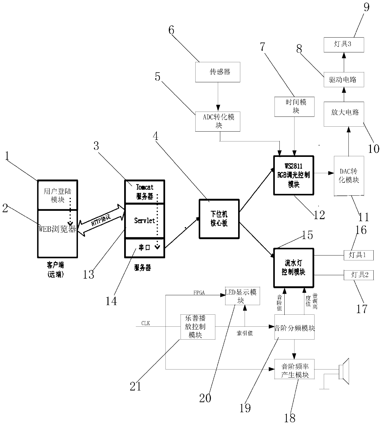
[0056] Such as figure 1 As shown, the WEB-based lighting control system provided by the embodiment of the present invention includes: user login module 1, WEB browser 2, Tomcat server 3, lower computer core board 4, ADC conversion module 5, sensor 6, time module 7, driver Circuit 8, third lamp 9, amplifier circuit 10, DAC conversion module 11, WS2811RCB dimming control module 12, Servlet 13, serial port 14, water lamp control module 15, first lamp 16, second lamp 17, scale frequency generati...


PUM


Abstract

The invention belongs to the field of lamplight control, and discloses a WEB-based lamplight control system. The WEB-based lamplight control system is provided with a user login module, wherein the user login module interacts with a WEB browser, the WEB browser is connected with a Servlet background service program on a Tomcat server by means of an HTTP protocol, and the Servlet background serviceprogram is connected with a lower computer core board via a serial port; the lower computer core board is connected with a WS2811RCB light modulation control module and a waterfall light control module, and the waterfall light control module is connected with a first lamp and a second lamp. The WEB-based lamplight control system has high expansibility and adaptability for lamplight control, and can be applied to lamplight control in various occasions (such as stage and factory); the WEB-based lamplight control system combines the Internet with the lamplight control technology, and realizes remote wireless control of lamplight; and the color of lamplight is modulated by means of a combination of sensors and time.

Description

technical field [0001] The invention belongs to the field of light control, and in particular relates to a WEB-based light control method and system. Background technique [0002] At present, the existing technologies commonly used in the industry are as follows: [0003] Lighting is an important symbol of human civilization and affects all aspects of people. Nowadays, there are various types and forms of lighting equipment, and the lighting control requirements and control forms of various scenes (such as: stage lighting, urban street lighting, etc.) are also different. How to quickly organize and control specific lighting equipment to produce various desired lighting effects in a specific scene is the main content of traditional lighting control technology research. However, with the rapid development of Internet technology, the combination of Internet and lighting control technology to realize remote wireless control of lighting is gradually becoming a research hotspot. ...

Claims


Application Information

Patent Timeline
Patent Type & Authority Applications(China)
IPC IPC(8): H05B37/02
CPCY02B20/40
Inventor 刘明远
Owner 刘明远
Learn More