
Self-positioning mounting steel wood energy dissipation combined joint

A combined node and self-positioning technology, which is applied to building components, building types, earthquake resistance, etc., can solve problems such as various tooth plate connection configurations, wood damage of bolted connection nodes, yield failure of nails or screws, etc., to improve energy consumption capacity , The energy consumption mechanism is clear, and the effect of improving the shear performance

Active Publication Date: 2019-06-04
SOUTHEAST UNIV
View PDF10 Cites 3 Cited by
  • Summary
  • Abstract
  • Description
  • Claims
  • Application Information

AI Technical Summary

Problems solved by technology

[0003] At present, the joint forms of modern wood structures mainly include nail (bolt) connection and tooth plate connection, etc. The existing problems are: (1) The positioning of beams and columns connected by nails or bolts needs to be accurate, otherwise the joint connection will be difficult; (2) Nail and bolt connection joints are prone to wood damage or nail or screw yield failure, etc., and it is difficult to repair after the earthquake, and there is no clear local ductile energy dissipation mechanism; (3) tooth plate connection configurations are diverse, and there is no clear and stable energy dissipation ability

Method used


Image

  • Self-positioning mounting steel wood energy dissipation combined joint
  • Self-positioning mounting steel wood energy dissipation combined joint
  • Self-positioning mounting steel wood energy dissipation combined joint

Examples


Embodiment 2

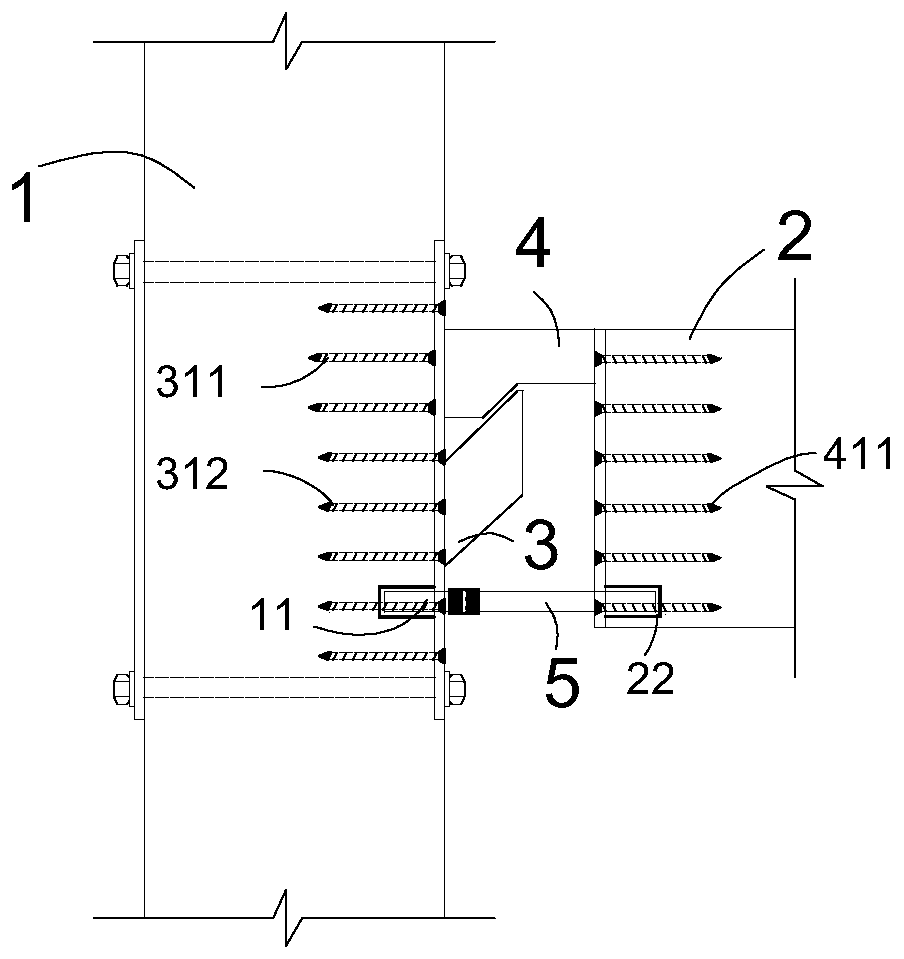
[0029] Such as Figure 6-8 The difference between this embodiment and Embodiment 1 is that the steel wedge hanging 4 bottom can be welded with a stiffening plate 43, the right side of the stiffening plate 43 is consolidated with the end steel plate 41 of the steel wedge hanging 4, and the upper side is connected with the steel wedge hanging 4 The oblique wedge surface 424 and the transitional horizontal bottom surface 425 are consolidated, and the corresponding groove 33 is opened on the steel support 3 corresponding to the stiffening plate 43 .

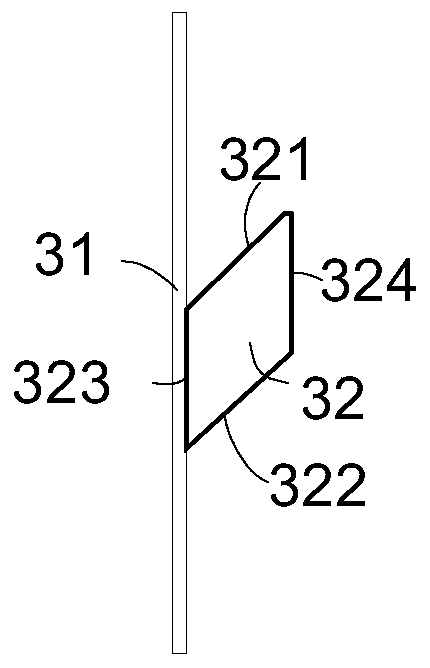
[0030] Such as Figure 9 , when the vertical column 1 and the horizontal beam 2 are in place, after the wooden beam is put in, driven by the load-bearing of the wooden beam, the inclined wedge surface 424 of the steel wedge hanger 4 and the inner inclined support surface of the steel inclined support 3 The relative sliding of 321 can make the vertical column 1 and the horizontal beam 2 self-positioning and installed.

[0031] Such ...


PUM


Abstract

The invention discloses a self-positioning mounting steel wood energy dissipation combined joint. The self-positioning mounting steel wood energy dissipation combined joint comprises vertical columns,horizontal beams, oblique bracket supports, steel wedge hangs and energy dissipation rods, the steel oblique bracket supports are composed of side steel plates and bracket supports, the steel obliquebracket supports are solidified to the side surfaces of the vertical wood columns through the side steel plates, the steel wedge hangs are composed of end steel plates and sphenocephalys, the steel wedge hangs are fixed to the end parts of the horizontal beams through the end steel plates, the energy dissipation rods are parallel to the beams and located on the lower parts, one ends of the energydissipation rods are solidified with the wood columns, and the other ends of the energy dissipation rods are solidified with the end parts of the horizontal beams. According to the self-positioning mounting steel wood energy dissipation combined joint, beam column mounting self-positioning can be driven by wood beam bearing, under the action of earthquake, the mounted energy dissipation rods canform hysteretic energy dissipation capacity through pull pressing depending on connection construction in the joint rotation process, replacement of the energy dissipation rods after earthquake is further facilitated, and rapid repair of the joint is realized.

Description

technical field [0001] The invention relates to an energy-consuming combined node, in particular to a self-positioning and installing steel-wood energy-consuming combined node. Background technique [0002] The traditional anti-seismic method for structures dissipates seismic energy through local yielding of the main structure, such as the beam-hinge mechanism. This method of anti-seismic energy consumption will lead to damage to the main body of the structure, increasing the difficulty and cost of post-earthquake repairs, and is not conducive to rapid post-earthquake repairs. . In recent years, the post-earthquake structure with zero damage, zero residual deformation, or very small damage, and a recoverable functional structural system that can be put into use with a little repair has attracted extensive attention from scholars and industries in various countries. The modern concept of shock absorption has gradually changed from traditional component energy dissipation to ...

Claims


Application Information

Patent Timeline
Patent Type & Authority Applications(China)
IPC IPC(8): E04H9/02E04B1/98
Inventor 王春林赵京练强曾滨
Owner SOUTHEAST UNIV
Learn More