Lifting platform for electric automobile overhauling
A technology of electric vehicles and lifting platforms, which is applied in the direction of lifting frames, lifting devices, tool storage devices, etc., can solve the problems of reducing the practicality of lifting platforms for car maintenance, vehicle falling, and personnel injuries, so as to ensure the stability of placement, Easy to take and ensure reliability
- Summary
- Abstract
- Description
- Claims
- Application Information
AI Technical Summary
Problems solved by technology
Method used
Image


Examples
Embodiment 1
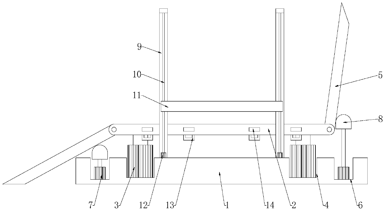
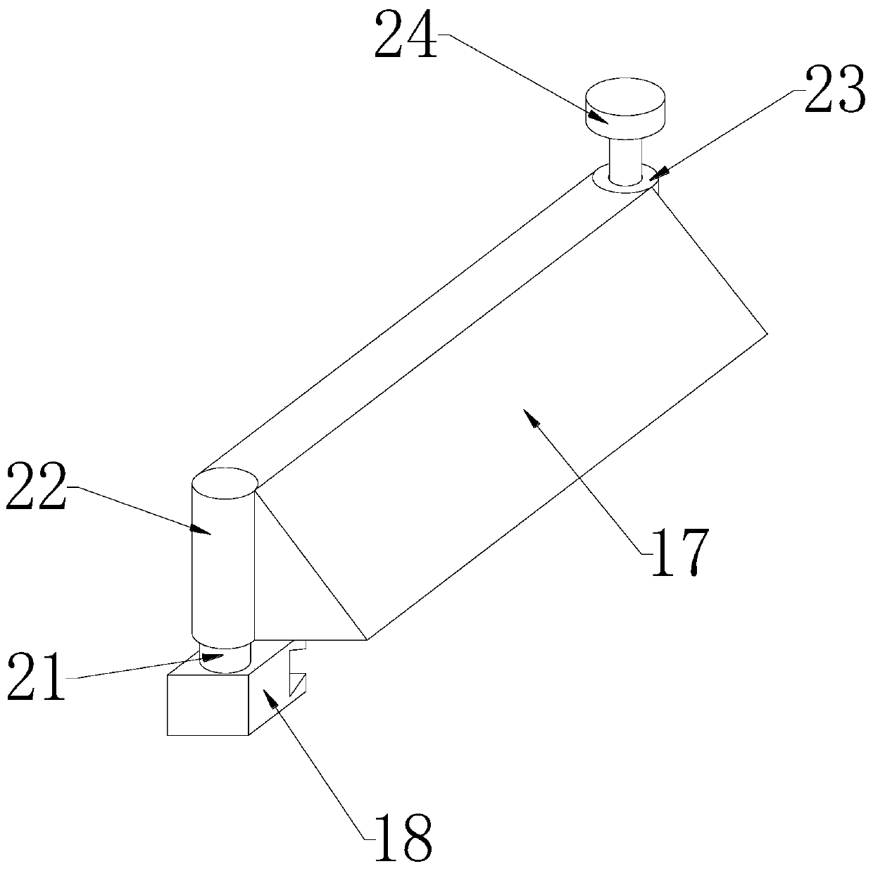
[0027] Reference Figure 1-3 , A lifting platform for electric vehicle maintenance, including a base 1, a supporting plate 2 and an inclined plate 5. Two supporting plates 2 are symmetrically arranged on both sides of the base 1, and the supporting plate 2 is fixedly installed on the base 1 through a hydraulic cylinder 3 The two ends of the support plate 2 are hinged with a sloping plate 5 through a hinge shaft. The sides of the opposite sides of the two support plates 2 are welded with a slide rail 16. The slide rail 16 is covered with a slider 18, and the top of the slider 18 rotates. A wedge block 17 is installed. One end of the wedge block 17 close to the slider 18 is welded with a shaft sleeve 22. The shaft sleeve 22 is sleeved on the rotating shaft 21. The bottom of the rotating shaft 21 is fixedly connected to the slider 18 by welding, and the wedge block 17 is far away One end of the shaft sleeve 22 is welded with a cylinder 23, a plug pin 24 is inserted into the cylind...
Embodiment 2
[0030] Reference Figure 4 Two sets of support columns 9 are vertically fixed on both sides of the base 1. The support column 9 is provided with a slide rail 20 on the side close to the support plate 2, and the support plate 2 is welded on the side close to the slide rail 20 to match the slide rail 20. Equipped with slider two 19.
[0031] Reference Figure 4 The support column 9 is far away from the support plate 2 and a screw rod 10 is installed through the bearing seat. The bottom of the screw rod 10 is fixedly connected with the output shaft of the rotating motor 12 through a coupling. The rotating motor 12 is fixedly installed at the bottom of the support column 9, one set A tool holder 11 is arranged between the supporting columns 9, a threaded block 25 is welded on the side of the tool holder 11 close to the supporting column 9, and the threaded block 25 is threadedly connected with the screw rod 10.
[0032] Reference Figure 4 , The tool rack 11 is a tray-shaped design wit...
Embodiment 3
[0035] Reference Figure 5 , The top block 8 is arranged under the inclined plate 5, the upper surface of the top block 8 is a curved surface design, the top block 8 is fixed on the top of the hydraulic cylinder two 7 by bolts or welding, the hydraulic cylinder two 7 is provided with two groups, one Two sets of hydraulic cylinders 7 are two, and two sets of hydraulic cylinders 7 are respectively symmetrically distributed at the four corners of the base 1, and connecting rods 26 are welded between the two top blocks 8 at the same end.
[0036] Reference figure 2 , The bottom of the support plate 2 is welded with multiple sets of fixing rings 13, and a fixing belt 15 is fixed on the fixing ring 13.
[0037] Reference figure 1 There are two sets of hydraulic cylinders one 3, one set of hydraulic cylinders one 3 is located under a supporting plate 2, the hydraulic cylinder one 3 is installed in the groove one 4, and the groove one 4 is opened on the base 1.
[0038] Reference figure 1 ,...
PUM
 Abstract
Description
Claims
Application Information
 - R&D
- Intellectual Property
- Life Sciences
- Materials
- Tech Scout
- Unparalleled Data Quality
- Higher Quality Content
- 60% Fewer Hallucinations
Browse by: Latest US Patents, China's latest patents, Technical Efficacy Thesaurus, Application Domain, Technology Topic, Popular Technical Reports.
© 2025 PatSnap. All rights reserved.Legal|Privacy policy|Modern Slavery Act Transparency Statement|Sitemap|About US| Contact US: help@patsnap.com