
Colloid jet printing head and colloid jet method

A technology of jet printing and colloid, which is applied to the device and coating of the surface coating liquid, which can solve the problems of large difference in dispensing accuracy, difficult cutting of colloid, and low operating frequency, so as to improve operating efficiency and easy cutting , the effect of small motion inertia

Active Publication Date: 2021-10-22
HARBIN INST OF TECH SHENZHEN GRADUATE SCHOOL
View PDF5 Cites 0 Cited by
  • Summary
  • Abstract
  • Description
  • Claims
  • Application Information

AI Technical Summary

Problems solved by technology

One way is to fix the workpiece to be glued or repaired, and drop the glue onto the working surface by manual dispensing. This method has low work efficiency, takes a long time to work, and the dispensing accuracy of different operators is quite different, so it is not applicable. For fine work, such as wafer packaging of chips or repair of the inner insulation layer of solid rocket motor; another way is to use contact needle dispensing device, by controlling the pneumatic or electric dispensing valve of contact needle dispensing device The opening and closing of the dispensing valve achieves the output and shutdown of the colloid, so that the colloid is pressed out of the container and dripped onto the working surface through the needle. Due to the low action frequency of the pneumatic or electric dispensing valve, the operation takes a long time and the efficiency is low. When the colloid is shot out from the container, the colloid is not easy to cut off, and it is easy to cause the colloid to flow back, and the distance between the needle of the contact needle dispensing device and the working surface is very close, and the colloid may flow out in long strips due to adhesion, causing the colloid not to flow out. Uniform, also not suitable for fine work

Method used


Image

  • Colloid jet printing head and colloid jet method
  • Colloid jet printing head and colloid jet method
  • Colloid jet printing head and colloid jet method

Examples


Embodiment Construction

[0043] Exemplary embodiments of the present disclosure will be described in more detail below with reference to the accompanying drawings. Although exemplary embodiments of the present disclosure are shown in the drawings, it should be understood that the present disclosure may be embodied in various forms and should not be limited by the embodiments set forth herein. Rather, these embodiments are provided for more thorough understanding of the present disclosure and to fully convey the scope of the present disclosure to those skilled in the art.

[0044] Reference will now be made in detail to the exemplary embodiments, examples of which are illustrated in the accompanying drawings. When the following description refers to the accompanying drawings, the same numerals in different drawings refer to the same or similar elements unless otherwise indicated. The implementations described in the following exemplary examples do not represent all implementations consistent with the ...


PUM


Abstract

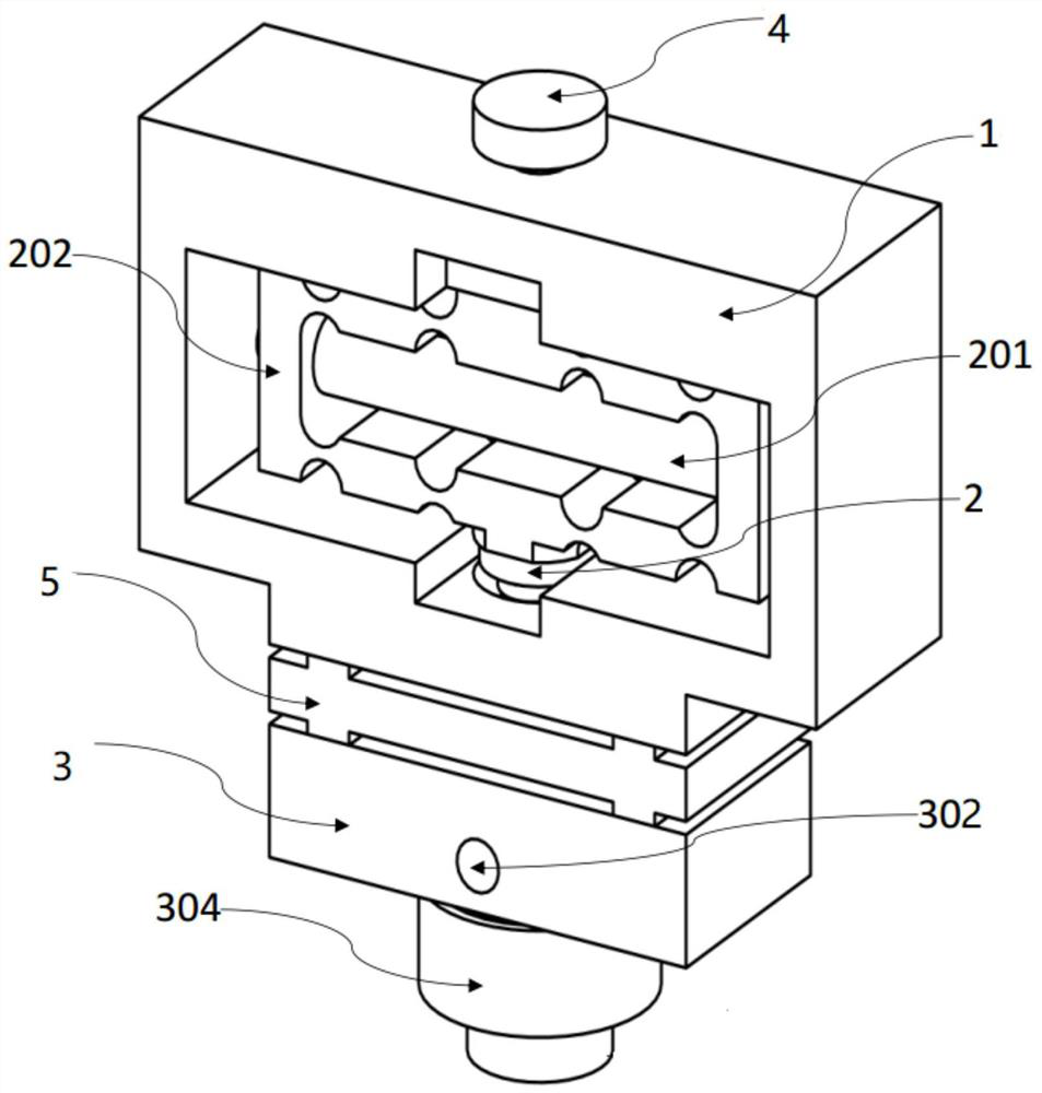
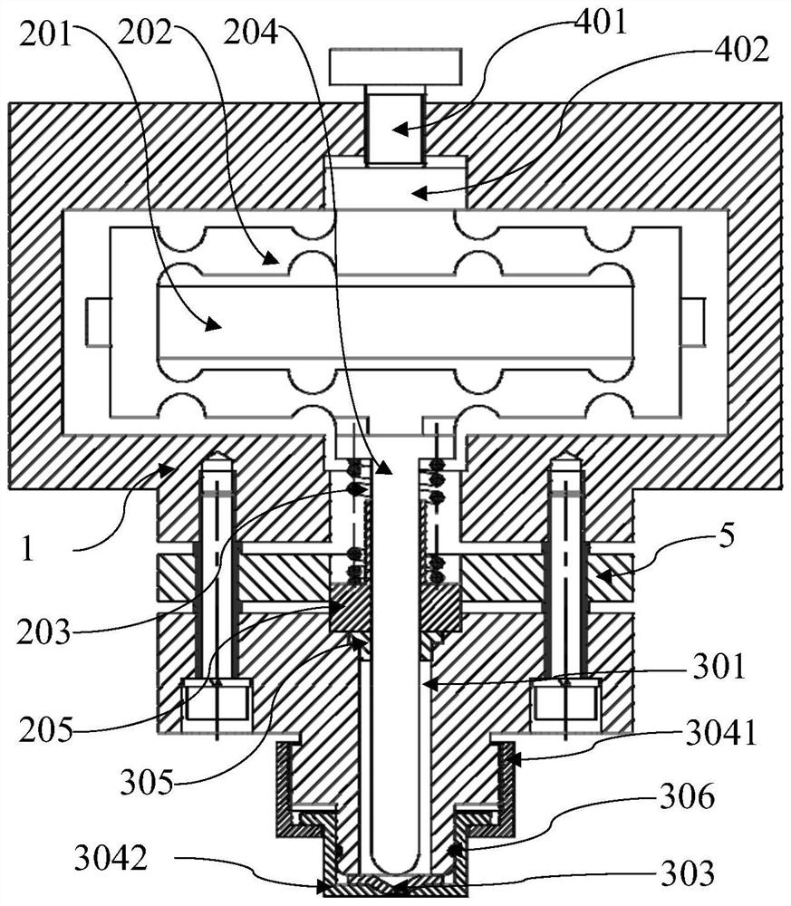
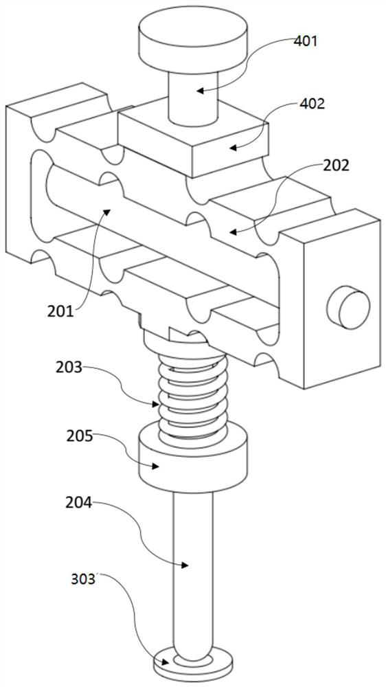
The invention discloses a colloid jet printing head, which comprises: a base body, a base connected to the base body, and a piezoelectric driving device arranged on the base body; the base includes a colloid flow channel, a liquid injection port and a nozzle at the bottom of the flow channel; The piezoelectric driving device includes: a piezoelectric ceramic column, a displacement amplifier and a striker, the displacement amplifier is in contact with the top of the striker, and the lower part of the striker is accommodated in the flow channel of the base; the piezoelectric ceramic column is in contact with the top of the striker. Driven by the high-frequency voltage pulse, the high-frequency expansion and contraction drives the movement of the displacement amplifier, and the displacement amplifier drives the striker to move periodically in the flow channel and strike the nozzle, ejecting the colloid in the nozzle to form liquid droplets. The invention also discloses a colloid jetting method. The invention solves the problems of long colloid jetting operation, low efficiency, uneven colloid and unsuitability for refined operation in the prior art.

Description

technical field [0001] The invention relates to a colloid jet printing head and a colloid jet method. Background technique [0002] In the prior art, adhesives are used to bond different materials, different thicknesses, ultra-thin specifications and complex workpieces, or to repair the inner heat insulation layer of the engine. One way is to fix the workpiece to be glued or repaired, and drop the glue onto the working surface by manual dispensing. This method has low work efficiency, takes a long time to work, and the dispensing accuracy of different operators varies greatly, so it is not applicable For fine work, for example, wafer packaging of chips or repair of inner insulation layer of solid rocket motor; another way is to use contact needle dispensing device, by controlling the pneumatic or electric dispensing valve of contact needle dispensing device The opening and closing of the dispensing valve achieves the output and shutdown of the colloid, so that the colloid i...

Claims


Application Information

Patent Timeline
Patent Type & Authority Patents(China)
IPC IPC(8): B05C5/02B05C11/10B05C11/00
Inventor 胡泓邵俊豪雷国斌
Owner HARBIN INST OF TECH SHENZHEN GRADUATE SCHOOL
Learn More