The invention discloses an optical screen structure of an ultrathin laser television

A technology of laser TV and screen structure, applied in the direction of TV, color TV, color TV components, etc., can solve the problems of thick screen structure, very high requirements, increase the thickness and strength of structural parts, etc., to reduce the thickness of the screen, guarantee The effect of flatness and improving assembly efficiency

Inactive Publication Date: 2019-05-31
SICHUAN CHANGHONG ELECTRIC CO LTD
View PDF7 Cites 5 Cited by
  • Summary
  • Abstract
  • Description
  • Claims
  • Application Information

AI Technical Summary

Problems solved by technology

[0002] Laser TV usually adopts ultra-short-throw projection, and the projection ratio is usually ≤0.233. The product is usually placed on the customer's TV cabinet or hoisted directly above the screen. It is precisely because of the characteristics of ultra-short-throw projection that the projection size is generally super large: 70~ 300-inch class, which has very high requirements for the flatness of the screen or projection surface; in order to ensure the flatness and strength of the screen, the traditional laser TV optical screen in the industry usually uses aluminum honeycomb board as the base material, and adopts riveting method on the back of the honeycomb board Install the suspension structural parts for suspension, and the main body of the screen undertakes the gravity of the screen itself; or adopt the method of increasing the thickness and strength of the structural parts, use springs, magic stickers, etc. to tension the screen optical diaphragm, and the screen frame undertakes the hanging screen itself Gravity, the thickness of the screen is mostly above 15mm, there is a disadvantage that the screen structure is relatively thick, which is not conducive to improving the overall appearance of the TV

Method used


Image

  • The invention discloses an optical screen structure of an ultrathin laser television
  • The invention discloses an optical screen structure of an ultrathin laser television
  • The invention discloses an optical screen structure of an ultrathin laser television

Examples


Embodiment 1

[0030] In this embodiment, a 100-inch ultra-thin laser TV screen will be used as a specific embodiment to illustrate the technical solution of the present invention.

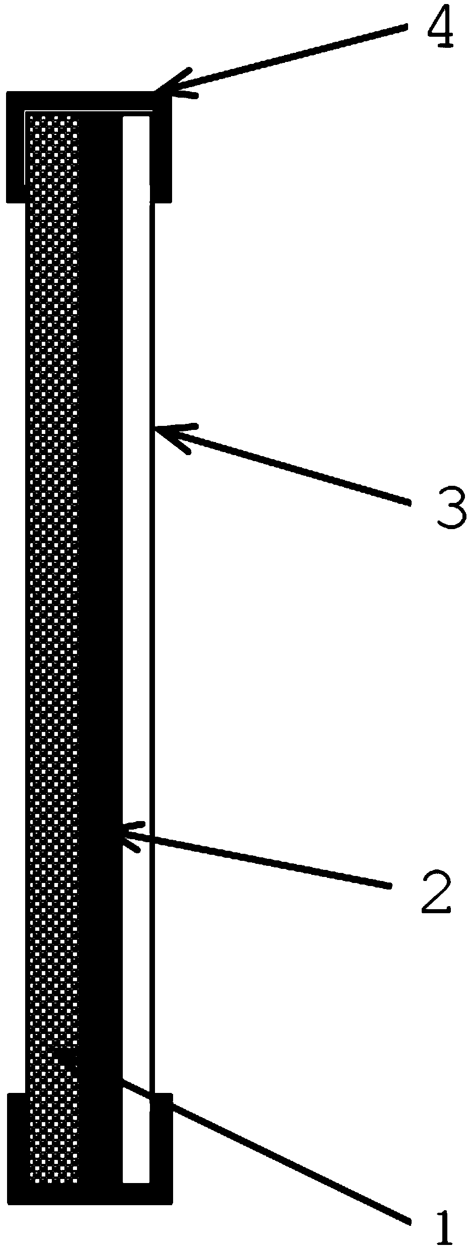
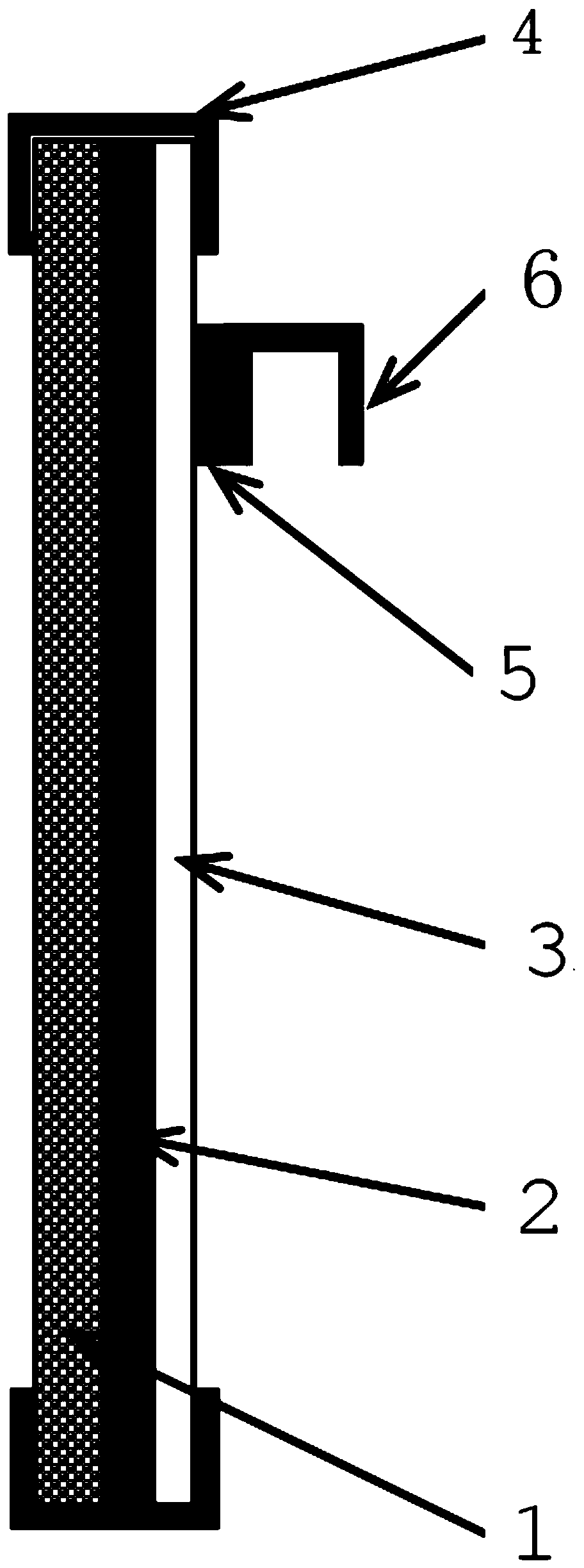
[0031] Such as figure 1 and image 3 As shown, an ultra-thin laser TV optical screen structure includes: a projection optical film 1, a support backplane 3, a decorative surface frame 4, a first adhesive 2, a second adhesive 5 and a hanger assembly 6, Wherein, the projection optical film 1 is bonded to the front of the support backplane 3 by the first adhesive 2, and the hanger assembly 6 is fixed on the back of the support backplane 3. In this embodiment, the hanger assembly 6 is specifically bonded by the second adhesive The adhesive 5 is bonded and fixed on the back of the support backboard 3 , in practice, it can also be fixed by means of riveting, screwing or the like.

[0032] The decorative surface frame 4 is wrapped around the end of the screen main body formed by the projection optical film 1, the fir...

Embodiment 2

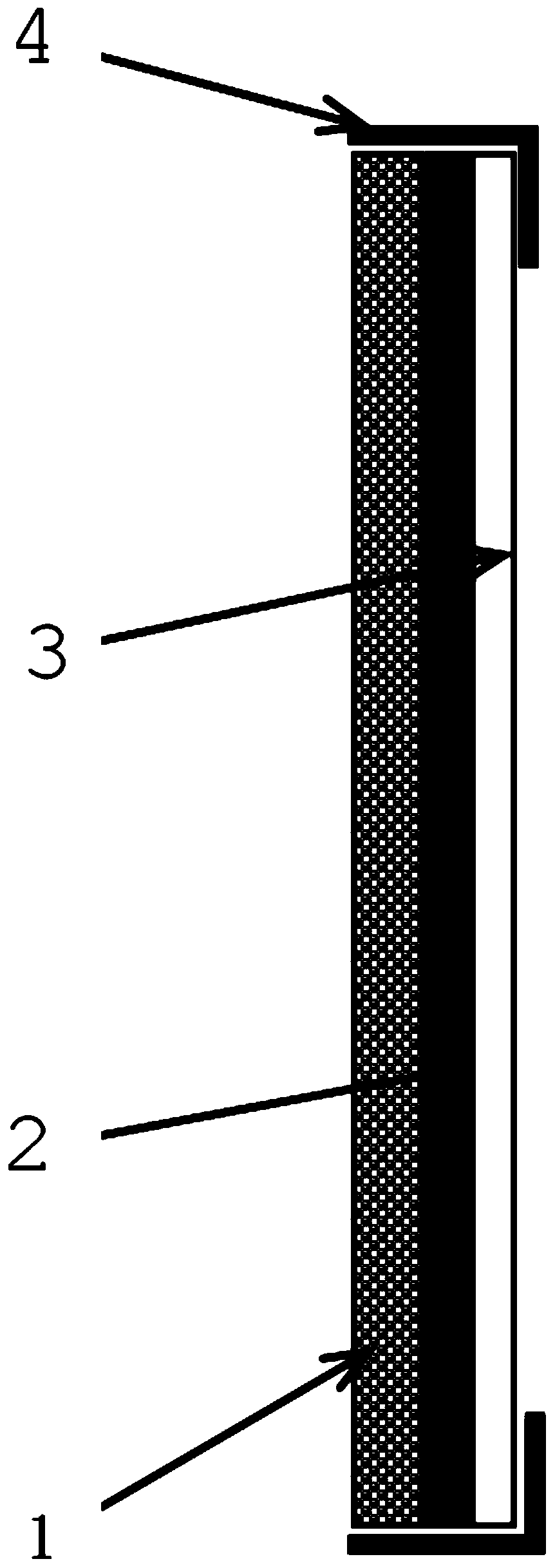
[0038] Such as figure 2 and Figure 4 As shown, the difference between this embodiment and Embodiment 1 is that the cross-sectional shape of the decorative surface frame 4 in this embodiment is L-shaped, and in this embodiment, two sets of hanger assemblies 6 are arranged on the back of the supporting backboard 3 In order to achieve a better installation and fixing effect.

Embodiment 3

[0040] Such as Figure 5 and Figure 6 As shown, the difference between the present embodiment and the second embodiment is that in the present embodiment, the hanger assembly 6 includes a soft magnet mounting frame (not shown in the figure) and a magnetic hanging frame 61, and the soft magnetic body mounting frame is compatible with the magnetic mounting frame. The hanger 61 is magnetically connected and fixed by riveting, screwing or bonding. The soft magnetic mounting frame is directly fixed on the screen mounting surface, and then the soft magnetic mounting frame and the magnetic hanging frame 61 are used to fix and support the ultra-thin screen. Laser TV optical screen structure.

[0041] In this embodiment, the support backboard 3 is made of non-ferrous or magnetic material, so the magnetic hanger 61 of the hanger assembly 6 is still glued and fixed on the back of the support backboard 3 by the second adhesive 5 .

[0042] In practice, the support backboard 3 can be ma...


PUM


Abstract

The invention discloses an optical screen structure of an ultrathin laser television. The optical screen structure comprises a projection optical film, a supporting back plate, a first adhesive and ahanging frame assembly, The projection optical film is bonded to the front face of the supporting back plate through a first adhesive, and the hanger assembly is fixed to the back face of the supporting back plate. According to the optical screen structure of the ultra-thin laser television, the thicknesses of the ultra-large-size screen main body and the frame can be reduced to be within 6mm, andthe ultra-large-size, ultra-narrow-frame and ultra-thin full-screen design of the laser television screen is realized while the flatness of the screen main body is ensured.

Description

technical field [0001] The invention relates to the technical field of image display, in particular to an ultra-thin laser TV optical screen structure. Background technique [0002] Laser TV usually adopts ultra-short-throw projection, and the projection ratio is usually ≤0.233. The product is usually placed on the customer's TV cabinet or hoisted directly above the screen. It is precisely because of the characteristics of ultra-short-throw projection that the projection size is generally super large: 70~ 300-inch class, which has very high requirements for the flatness of the screen or projection surface; in order to ensure the flatness and strength of the screen, the traditional laser TV optical screen in the industry usually uses aluminum honeycomb board as the base material, and adopts riveting method on the back of the honeycomb board Install the suspension structural parts for suspension, and the main body of the screen undertakes the gravity of the screen itself; or a...

Claims


Application Information

Patent Timeline
IPC IPC(8): H04N5/64H04N21/41H04N9/31
Inventor 赵海龙岳定飞李志翔张兵
Owner SICHUAN CHANGHONG ELECTRIC CO LTD
Why Eureka
Try Eureka