Multi-source heat supply system

A technology for a heating system and a control system, applied in the field of composite source heating systems, can solve the problems of wind power curtailment, wind energy resource waste, etc.

Pending Publication Date: 2019-05-31
北控清洁热力有限公司
View PDF7 Cites 0 Cited by
  • Summary
  • Abstract
  • Description
  • Claims
  • Application Information

AI Technical Summary

Problems solved by technology

[0004] The purpose of the present invention is to provide a composite source heating system to solve the problem in the prior art that during the winter heating period, a large number of wind turbines abandon wind and limit electricity, resulting in a huge waste of wind energy resources

Method used


Image

  • Multi-source heat supply system

Examples


Embodiment Construction

[0025] In order to make the technical problems solved by the present invention, the technical solutions adopted and the technical effects achieved clearer, the technical solutions of the present invention will be further described below in conjunction with the accompanying drawings and through specific implementation methods. It should be understood that the specific embodiments described here are only used to explain the present invention, but not to limit the present invention. In addition, it should be noted that, for the convenience of description, only the parts related to the present invention are shown in the drawings but not all of them.

[0026] In the description of the present invention, unless otherwise clearly specified and limited, the terms "connected", "connected" and "fixed" should be understood in a broad sense, for example, it can be a fixed connection, a detachable connection, or an integrated ; It can be a mechanical connection or an electrical connection;...


PUM


Abstract

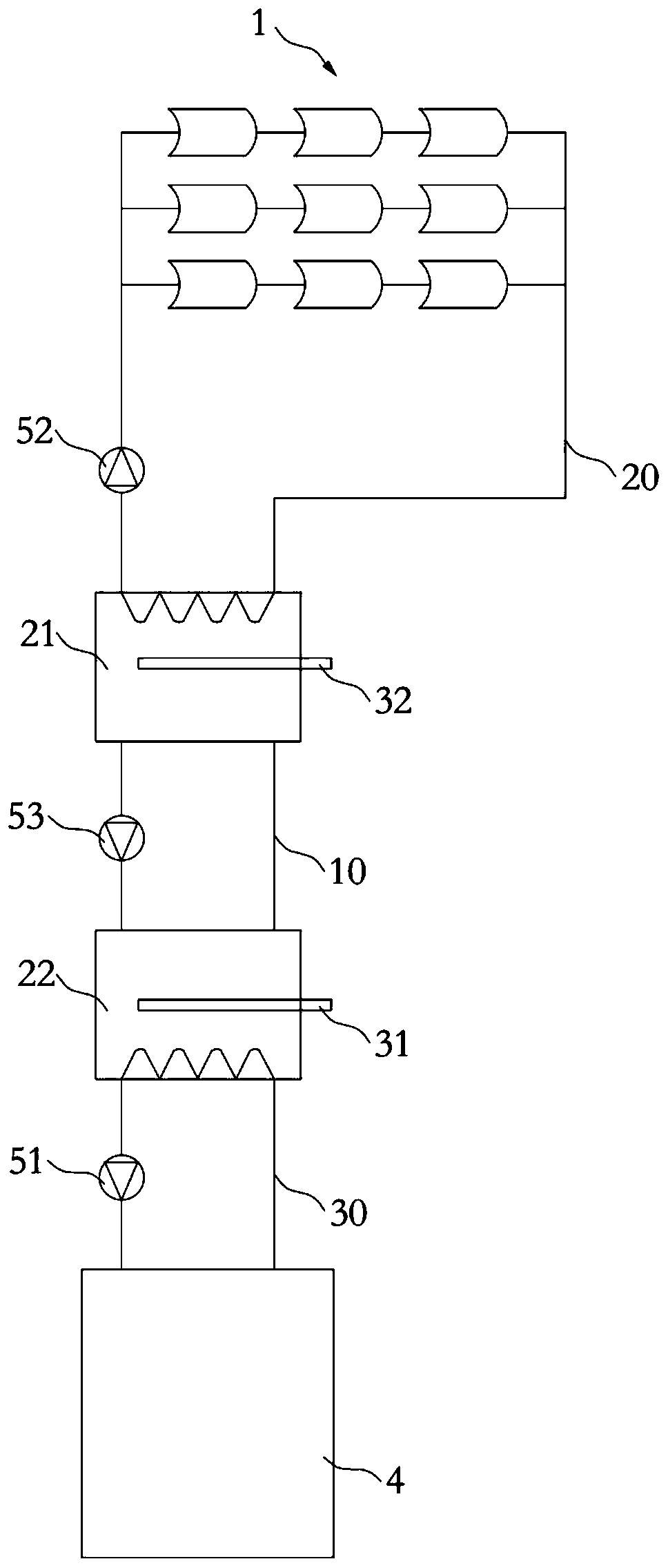
The invention discloses a multi-source heat supply system which belongs to the technical field of heat supply equipment and comprises a phase change energy storage tank, a constant temperature energystorage tank, a solar thermal collector and a first electric heater, wherein the phase change energy storage tank and the constant temperature energy storage tank are filled with a phase change material, and a circulation loop is formed between the phase change energy storage tank and the constant temperature energy storage tank via a first pipeline; a second pipeline is connected between a mediuminlet of the solar thermal collector and a medium outlet of the solar thermal collector, the second pipeline is filled with a working medium and a part of the second pipeline is located in the phasechange energy storage tank; and the first electric heater is disposed in the constant temperature energy storage tank. The multi-source heat supply system disclosed by the invention has the advantagesthat the system can make full use of solar energy for heat supply in the daytime and storage surplus thermal energy; and at night, the system can supply and store the thermal energy by making use ofpower generated by a generating set or off-peak electricity at night, so wind abandoning and electricity limiting of a wind generation set are avoided and the use ratio of wind energy and solar energyis increased.

Description

technical field [0001] The invention relates to the technical field of heating equipment, in particular to a composite source heating system. Background technique [0002] In areas with rich wind energy resources in my country, wind energy resources are abundant, and the scale of wind power installed capacity is increasing continuously to improve the utilization rate of wind energy. [0003] However, during the winter heating period, when there is a strong wind in the north, the combined heat and power unit must ensure stable operation, and the power generation load increases in a large area, making it more difficult to adjust the peak of the power grid, especially at night, which is the peak of heating and heating. In the trough stage of electricity load, and because the price of thermal power is lower than that of wind power, wind turbines have to abandon wind and limit power in large quantities, resulting in a great waste of wind energy resources. Contents of the invent...

Claims


Application Information

Patent Timeline
IPC IPC(8): F24D11/00F24D19/00F24D19/10F24S20/40F24S60/10
CPCY02E10/40Y02B10/20Y02B10/70
Inventor 纪格文王英俊丁鹏民康金松江维光贾宝荣张盼荣
Owner 北控清洁热力有限公司
Why Eureka
Try Eureka