
Storage battery test rack

A test rack and storage battery technology, applied in the direction of measuring electricity, measuring devices, measuring electrical variables, etc., can solve the problems of affecting indoor space utilization, large test rack volume, and large space occupation, and achieve simple structure, simple and flexible assembly, and The effect of reducing the occupied space

Inactive Publication Date: 2019-05-28
王韬
View PDF0 Cites 0 Cited by
  • Summary
  • Abstract
  • Description
  • Claims
  • Application Information

AI Technical Summary

Problems solved by technology

Generally, the same batch of batteries is placed on the test rack for testing. The traditional test rack is large in size and has a fixed structure. space utilization

Method used


Image

  • Storage battery test rack
  • Storage battery test rack
  • Storage battery test rack

Examples


Embodiment Construction

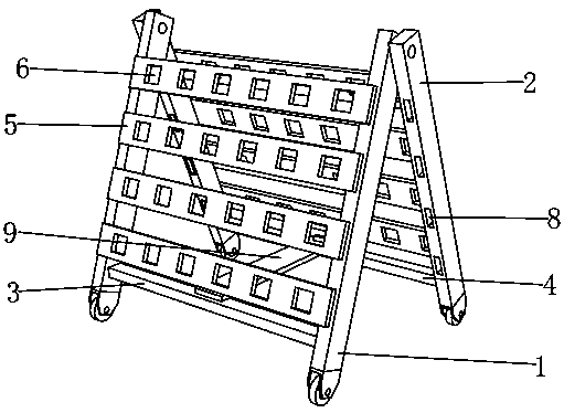
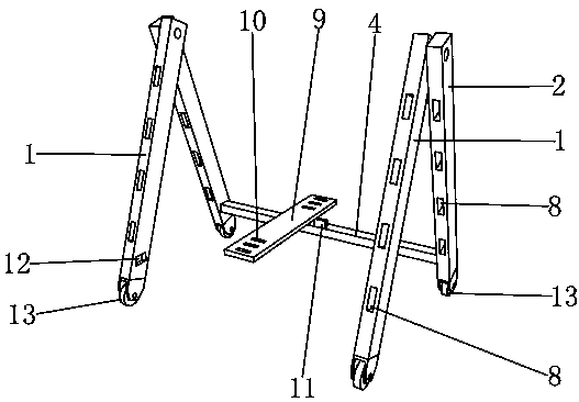
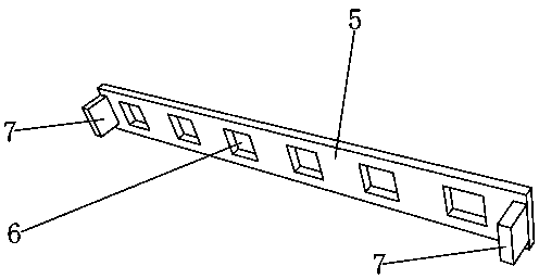
[0018] Such as Figure 1 to Figure 3 As shown, it is a battery test rack of the present invention, including a first pole 1 and a second pole 2, the first pole 1 is movably connected to the second pole 2, and a first fixed pole is provided between the first poles 1 Rod 3, a second fixed rod 4 is arranged between the second rods 2, a test board 5 is arranged between the first rods 1, a test board 5 is arranged between the second rods 2, and the test board 5 is evenly distributed There is a test bayonet 6, and the test bayonet 6 is used to fix the battery to be tested. Both ends of the test board 5 are provided with bumps 7, and both the first pole 1 and the second pole 2 are provided with a through card slot 8 , through the card slot 8 and connected to the protrusion 7, a limit plate 9 is provided between the first fixed rod 3 and the second fixed rod 4, and a limit groove 10 is arranged on the limit plate 9, and the limit groove 10 is symmetrically distributed, and the first f...


PUM


Abstract

The invention discloses a storage battery test rack which comprises first support rods and second support rods. The first support rods are movably connected with the second support rods, a first fixing rod is arranged between the first support rods, a second fixing rod is arranged between the second support rods, a test plate is arranged between the first support rods, a test plate is arranged between the second support rods, test bayonets are uniformly distributed on the test plates, convex blocks are arranged at two ends of each test plate, through clamping grooves are formed in the first support rods and the second support rods and are connected with the convex blocks, a limiting plate is arranged between the first fixing rod and the second fixing rod. The storage battery test rack hasthe advantages of simple structure, flexible connection, convenient assembly, small volume after disassembly and convenient storage.

Description

technical field [0001] The invention belongs to the technical field of testing auxiliary tools, in particular to a storage battery testing rack. Background technique [0002] After the battery is produced, performance testing is required, and it can only be packaged and sold after passing the test. Generally, the same batch of batteries is placed on the test rack for testing. The traditional test rack is large in size and has a fixed structure. Space utilization. Contents of the invention [0003] The purpose of the present invention is to solve the above-mentioned technical problems existing in the prior art, and provide a battery test rack with simple structure, flexible connection, convenient assembly, small volume after disassembly, and convenient storage. [0004] In order to solve the above technical problems, the present invention adopts the following technical solutions: [0005] A storage battery test frame, characterized in that it includes a first pole and a ...

Claims


Application Information

Patent Timeline
IPC IPC(8): G01R31/36G01R1/04
Inventor 不公告发明人
Owner 王韬
Learn More