
Joint and support pin assembly

A technology of supporting pins and assemblies, applied in interconnection systems, springs and suspensions made of plastic materials, etc., can solve the problems of limited service life, loss of pressure of the elastic body, easy detachment, etc., to achieve extended service life, convenient replacement effect

Pending Publication Date: 2019-05-28
QUANZHOU XINLONG AUTOMOBILE PARTS MFG CO LTD
View PDF1 Cites 0 Cited by
  • Summary
  • Abstract
  • Description
  • Claims
  • Application Information

AI Technical Summary

Problems solved by technology

[0003] This joint and support pin assembly has the following disadvantages: 1. The elastic body is formed by heating and vulcanizing after adding chemical raw materials to natural rubber, which not only causes waste of resources and energy, but also causes air pollution
2. Use natural rubber to bond with other parts to form a relatively integrated body after heating and vulcanization. After being subjected to external force, the rubber and other parts are easy to separate, that is, the stability of the structure is poor.
3. There is no limit protection for the elastic body. When the elastic body is subjected to external force, it is easy to be pulled and cracked, resulting in a short service life
However, when this joint and support pin assembly is assembled on the reaction rod of the vehicle, its rigid movable limit baffle is respectively movable and clamped in the installation hole of the rod head of the reaction rod on the outer periphery of the support pin in the radial direction. In actual use, the service life of the elastic body of the joint and support pin assembly is limited and needs to be replaced regularly. At this time, if the rod head of the reaction rod is deformed, the rigid movable limit baffle will be stuck on the reaction rod It is difficult to remove the joint and support pin assembly from the mounting hole of the rod head of the reaction rod and reinstall it for replacement.
In addition, the rigid movable baffle plate and the rigid fixed baffle plate are pressed against each other and used for friction in practical applications, and the two are very easy to wear and tear, resulting in the enlargement of the cavity for the elastic body, resulting in elastic The body loses pressure, and the service life of the joint and support pin assembly is short

Method used


Image

  • Joint and support pin assembly
  • Joint and support pin assembly
  • Joint and support pin assembly

Examples


Embodiment 1

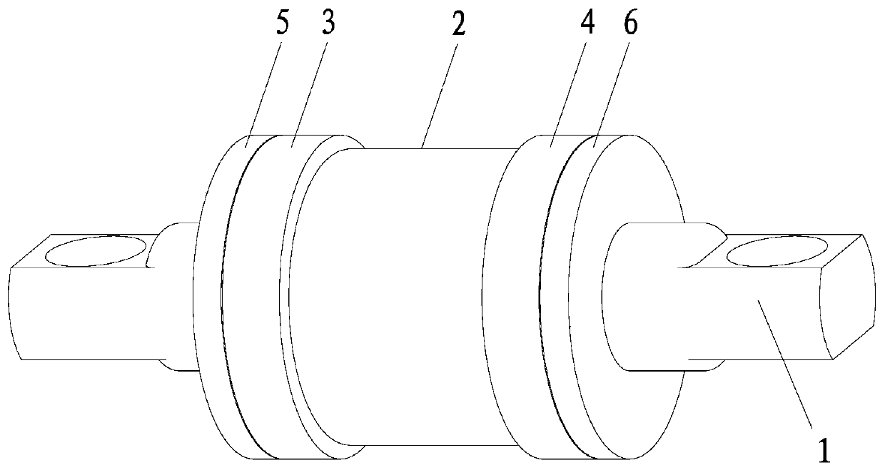
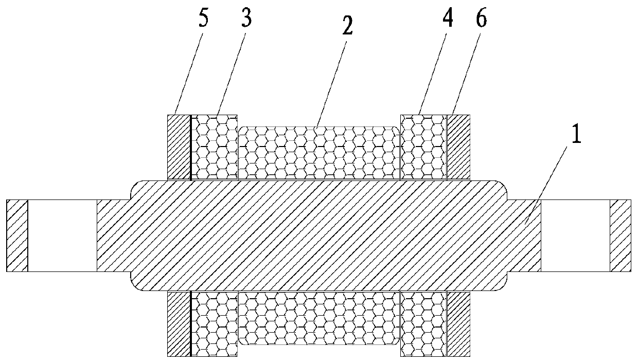
[0039] Joint and supporting pin assembly of the present invention, embodiment is as figure 1 and 2 As shown, it includes a support pin 1, an inner elastic body 2, a first outer elastic body 3, a second outer elastic body 4, a first rigid fixed baffle 5 and a second rigid fixed baffle 6; the inner elastic body 2 is tight It is wrapped on the cylindrical surface of the support pin 1 and is arranged corresponding to the axial middle section of the support pin 1; the first outer elastic body 3 and the second outer elastic body 4 are sleeved on the support pin On the bearing pin 1, and the axial inner end surfaces of the first outer elastic body 3 and the second outer elastic body 4 are respectively stacked on the axial end surfaces of the inner elastic body 2, the first outer elastic body The maximum radial dimension of the body 3 and the second outer elastic body 4 is larger than the maximum radial dimension of the inner elastic body 2; the first rigid fixed baffle 5 and the sec...

Embodiment 2

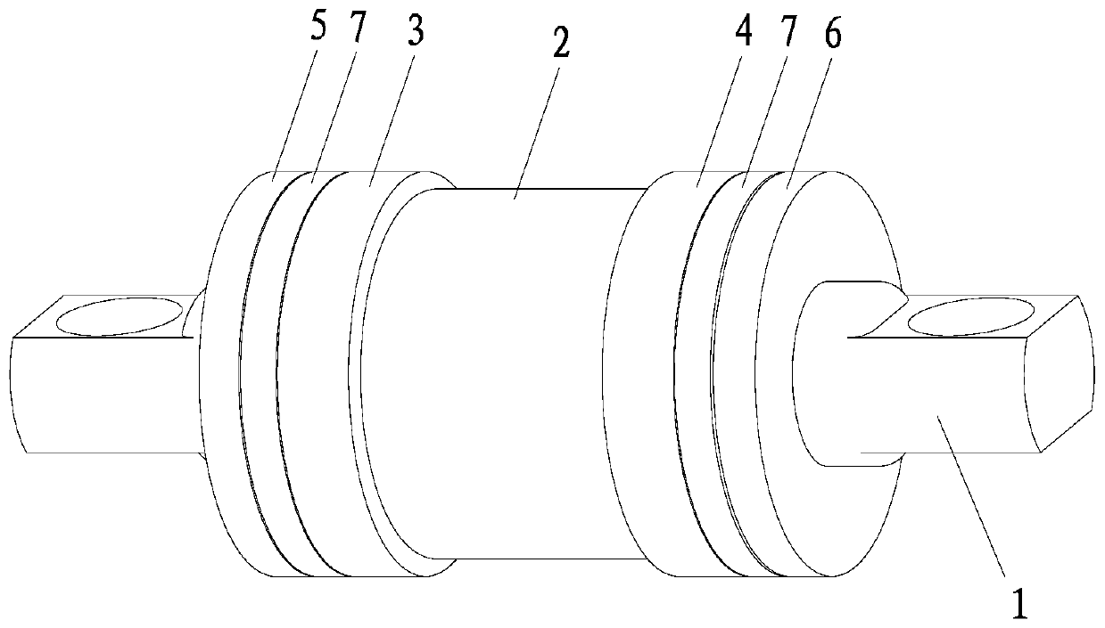
[0053] Joint and supporting pin assembly of the present invention, embodiment two such as image 3 and 4 As shown, the difference between this embodiment and Embodiment 1 is that it also includes a rigid movable washer 7, which is sleeved on the support pin 1 and placed on the first outer elastic body 3 and the second elastic body respectively. Between a rigid fixed baffle 5 and between the second outer elastic body 4 and the second rigid fixed baffle 6 . When the first rigid fixed baffle 5 or / and the second rigid fixed baffle 6 are installed on the support pin 1 in a detachable manner, especially when the first rigid fixed baffle 5 or / and the second rigid fixed baffle When the plate 6 is installed on the support pin by threaded connection, the rigid movable gasket 7 can effectively prevent the first rigid fixed baffle 5 or / and the second rigid fixed baffle 6 from rotating and loosening during work, thereby ensuring that the entire joint and The working reliability of the su...

Embodiment 3

[0056] Joint and supporting pin assembly of the present invention, embodiment three such as Figure 5 and 6 As shown, the difference between this embodiment and Embodiment 1 is that it also includes a rigid movable baffle 8, which is movably fitted on the supporting pin 1 and sandwiched between the first outer elastic body respectively. 3 and the inner elastic body 2 and between the second outer elastic body 4 and the inner elastic body 2; and the maximum radial dimension of the rigid movable baffle 8 is greater than that of the inner elastic body 2 Maximum radial dimension. When the joint and supporting pin assembly of the present invention are assembled on the rod head of the reaction rod, the rigid movable baffles 8 respectively abut against the axial two ends of the rod head of the reaction rod.

[0057] When working, when the inner elastic body 2 is radially squeezed, the inner elastic body 2 is extruded outward along the axial direction due to the restriction of the ro...


PUM


Abstract

The invention discloses a joint and support pin assembly. The joint and support pin assembly comprises a support pin, an inner elastic body, a first outer elastic body, a second outer elastic body, afirst rigid fixed baffle and a second rigid fixed baffle. The cylindrical surface of the support pin is tightly wrapped with the inner elastic body and the inner elastic body is arranged correspondingto the axial middle section of the support pin. The support pin is sleeved with the first outer elastic body and the second outer elastic body. The axial two end faces of the inner elastic body are correspondingly overlapped with axial inner end surfaces of the first outer elastic body and the second outer elastic body. The maximum radial dimension of the first outer elastic body and the second outer elastic body are both larger than the maximum radial dimension of the inner elastic body. The first rigid fixed baffle or / and the second rigid fixed baffle are detachably fixed on the support pinin a penetrating and sleeving manner, and the axial outer end surfaces of the first outer elastic body and the second outer elastic body are correspondingly overlapped with the axial inner end surfaces of the first rigid fixed baffle and the second rigid fixed baffle. The joint and support pin assembly has the beneficial effects of being convenient to replace and longer in service life.

Description

technical field [0001] The invention relates to a joint and a supporting pin assembly among the components of a reaction rod assembly of a rear suspension balance device of a vehicle chassis. Background technique [0002] The traditional joint and support pin assembly, its basic structure includes a support pin, an inner shell, an elastic body and an outer shell. In the inner casing, natural rubber and chemical raw materials are injected between the outer casing and the inner casing, and then heated and vulcanized to form an elastic body. Joint and support pin assembly have the functions of shock absorption and balance. During use, the outer casing is pressed into the installation hole of the rod head of the reaction rod along the axial direction of the support pin, so that the outer casing is tightly fitted and embedded in the installation hole of the rod head of the reaction rod. [0003] This joint and support pin assembly has the following disadvantages: 1. The elastic...

Claims


Application Information

Patent Timeline
Patent Type & Authority Applications(China)
IPC IPC(8): F16F1/38B60G21/04
CPCF16F1/38B60G21/04
Inventor 陈清欣陈静文陈佳杨陈佳盛
Owner QUANZHOU XINLONG AUTOMOBILE PARTS MFG CO LTD
Learn More