
Sewage treatment reaction tank and purification system for sewage treatment

A sewage treatment and purification system technology, applied in the direction of water/sewage multi-stage treatment, water/sludge/sewage treatment, water pollutants, etc., can solve the problems of high cost, inability to establish sewage treatment plants, and sewage cannot be treated in time, etc. question

Pending Publication Date: 2019-05-28
陈化
View PDF0 Cites 1 Cited by
  • Summary
  • Abstract
  • Description
  • Claims
  • Application Information

AI Technical Summary

Problems solved by technology

For example, market towns that have not built sewage treatment plants so far, produce common heavy metal ions or common toxic and harmful ions (such as cyanide CN - , Fluorine F - , Arsenic As 3+ 、As 5+ ) of scattered enterprises, landscape lakes that need to be treated to replace water sources, and aquaculture enterprises to produce wastewater, it is difficult to collect and treat all the sewage or wastewater from the above-mentioned sources due to the geographical location of the above-mentioned sources of sewage or wastewater; in addition, Landscape lakes generally have no idle land to build sewage treatment plants, and aquaculture enterprises may not be able to build sewage treatment plants due to construction investment and other reasons, resulting in sewage not being treated in time, or needing to use a large amount of high-quality tap water to replace polluted landscape lakes source of water
In addition, most of the existing sewage treatment equipment that adopts the sequencing batch activated sludge process to treat sewage currently use electromechanical rocker, sleeve, siphon, rotary and buoy type decanting devices, which need to be configured to collect water. Water device, connection device, transmission device or even some special drainage device, the structure of this kind of decanting device is relatively complicated and the cost is high

Method used


Image

  • Sewage treatment reaction tank and purification system for sewage treatment
  • Sewage treatment reaction tank and purification system for sewage treatment
  • Sewage treatment reaction tank and purification system for sewage treatment

Examples


Embodiment Construction

[0041] The present invention will be described in detail below with reference to the accompanying drawings and examples. It should be noted that, in the case of no conflict, the embodiments of the present invention and the features in the embodiments can be combined with each other. For the convenience of description, if the words "up", "down", "left" and "right" appear in the following, it only means that the directions of up, down, left and right are consistent with the drawings themselves, and do not limit the structure.

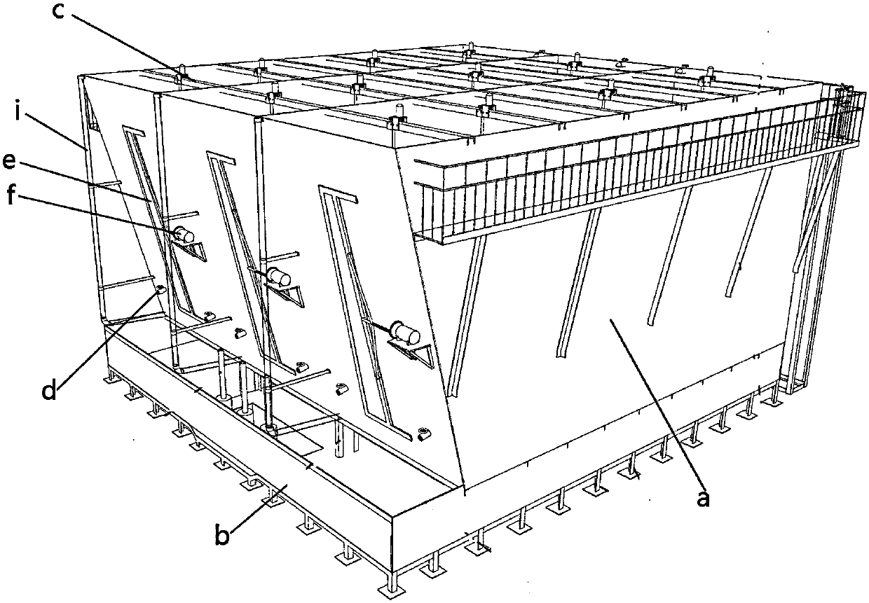
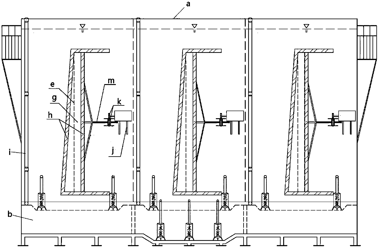
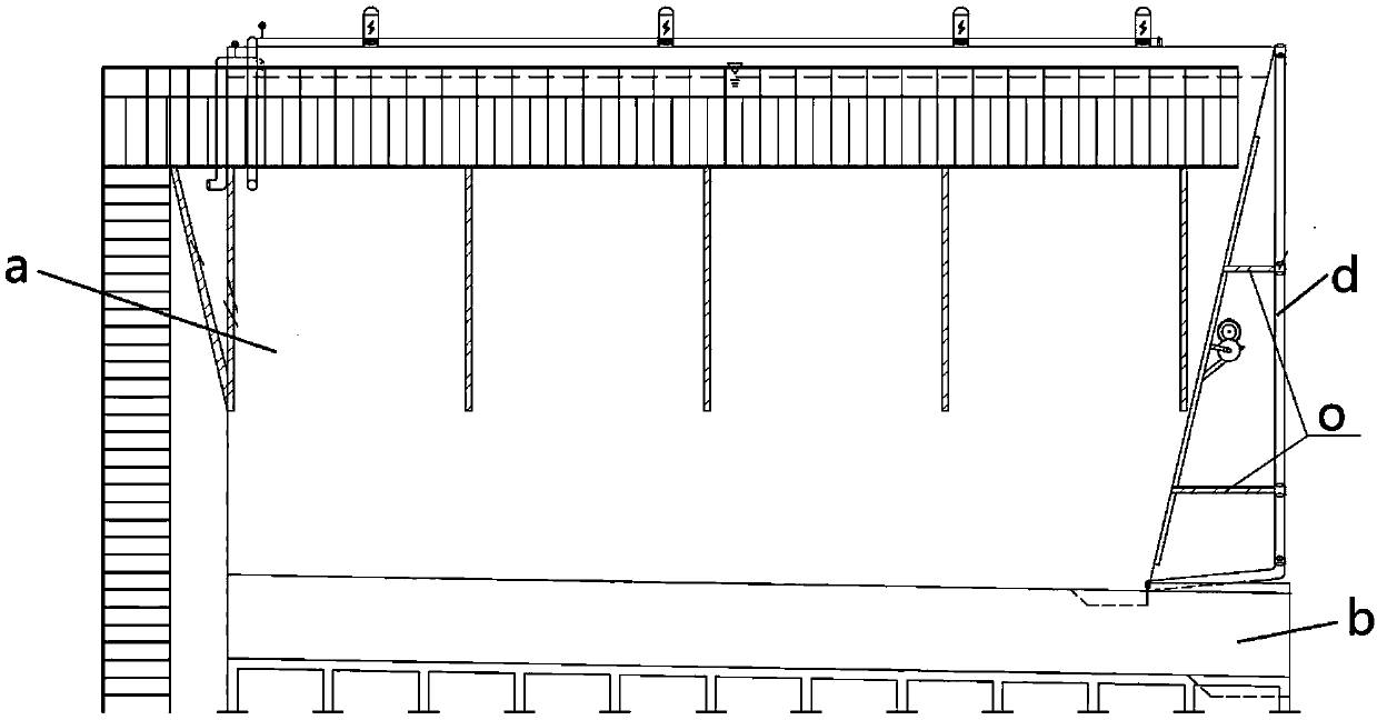
[0042] Such as Figure 1 to Figure 3 As shown, a sewage treatment reaction tank includes a pool body a, and a clear water storage pool b is provided below the pool body a; the pool body a has at least one inclined side, which gradually slopes toward the pool body from top to bottom , there are three gates g on the side, the projection of the gate g along the vertical direction is in the clear water storage pool b, the gate g is covered with a movable gat...


PUM


Abstract

The invention relates to a purification system for sewage treatment. The purification system comprises a first sewage treatment reaction tank, a second sewage treatment reaction tank, a quick filtering tank, a carbon filtering tank and a nano-sewage clarifying tank, wherein a clean water accommodation tank of the first sewage treatment reaction tank is communicated with a tank body of the second sewage treatment reaction tank through a pipeline with a water pump, a clean water accommodation tank of the second sewage treatment reaction tank is communicated with a liquid inlet of the quick filtering tank, and a filter liquid outlet of the filtering tank is communicated with a liquid inlet of the carbon filtering tank; a lower sludge outlet of the tank body of the first sewage treatment reaction tank and a lower sludge outlet of the tank body of the second sewage treatment reaction tank are respectively communicated with the nano-sewage clarifying tank. The purification system has the advantages that the sewage and wastewater can be separately treated, the limitation by the address selection of a sewage treatment factory is avoided, the cost is low, the separation effect is good, andthe good treatment effect is guaranteed; the treatment and purification functions are integrated, the pollution-free treatment is not simply performed on the sewage and wastewater, and the treated sewage and wastewater can be recycled as mixed water, so as to conserve the high-quality running water.

Description

technical field [0001] The invention relates to a sewage treatment reaction pool and a sewage treatment-purification system, in particular to a sewage treatment-purification system which can easily realize the decentralized treatment of sewage, and belongs to the field of environmental protection equipment. Background technique [0002] At present, sewage or wastewater treatment mainly relies on sewage treatment plants. The location of sewage treatment plants is relatively fixed. Sewage or wastewater in a certain area must be transported to sewage treatment plants through pipeline transportation and other channels to complete the treatment. Due to the source of sewage or wastewater The geographical location of the sewage treatment plant is scattered or lower than the height of the geographical location of the sewage treatment plant. It is quite limited to collect the sewage or wastewater within the jurisdiction of a certain sewage treatment plant. For example, market towns t...

Claims


Application Information

Patent Timeline
Patent Type & Authority Applications(China)
IPC IPC(8): C02F9/14C02F101/10C02F101/14C02F101/18C02F101/20
Inventor 陈化
Owner 陈化
Learn More