
High protection new energy charging pile and using method thereof

A charging pile, high-protection technology, applied in the field of high-protection new energy charging piles, can solve the problems of rising maintenance costs, easy accumulation of dust, damage, etc., to achieve the effect of ensuring service life, improving safety protection, and avoiding loss

Active Publication Date: 2019-05-28
昆山锐能新能源科技发展有限公司
View PDF6 Cites 6 Cited by
  • Summary
  • Abstract
  • Description
  • Claims
  • Application Information

AI Technical Summary

Problems solved by technology

[0003] With the continuous development and progress of society, people's pursuit of quality of life has gradually improved, and their awareness of environmental protection has become stronger and stronger. New energy vehicles are loved by people and have gradually entered people's lives. At present, most of the charging piles are basically exposed directly. Outdoors, it is often attacked by wind and rain, and dust is easy to accumulate on the surface. When dust enters the interior of the charging pile, it is easy to cause wear of internal parts or short circuit of components, which reduces the service life of the charging pile. Generally, there is no shelter around the charging pile objects, the safety protection performance is low, and when the charging pile is hit by a collision, it is easy to cause damage, resulting in an increase in maintenance costs

Method used


Image

  • High protection new energy charging pile and using method thereof
  • High protection new energy charging pile and using method thereof
  • High protection new energy charging pile and using method thereof

Examples


Embodiment Construction

[0039] The technical solutions of the present invention will be clearly and completely described below in conjunction with the embodiments. Apparently, the described embodiments are only some of the embodiments of the present invention, not all of them. Based on the embodiments of the present invention, all other embodiments obtained by persons of ordinary skill in the art without creative efforts fall within the protection scope of the present invention.

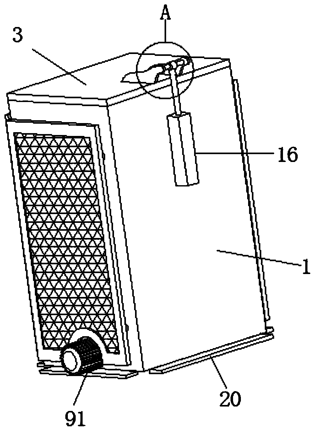
[0040] Such as Figure 1-7 As shown, the high-protection new energy charging pile includes a housing 1, a charging pile main body 2, a lifting assembly 9, an upper shock absorbing assembly 7 and a lower shock absorbing assembly 8, and the front and rear inner surfaces of the housing 1 are fixedly installed with two A lower fixed plate 12 and two upper fixed plates 13, and two lower fixed plates 12 and two upper fixed plates 13 are all symmetrically distributed, and a second fixed plate is vertically fixed between the descri...


PUM


Abstract

The invention discloses a high protection new energy charging pile and a using method thereof. The high protection new energy charging pile comprises a shell, a charging pile main body, a lifting assembly, an upper damping assembly and a lower damping assembly, wherein two lower fixed plates and two upper fixed plates are fixedly mounted on each of both front and rear inner surfaces of the shell;second sliding rods are vertically fixed between the lower fixed plates and the upper fixed plates; third baffles are fixedly mounted on both the front and rear inner surfaces of the shell; the uppersurface of the shell is hinged with a top cover board; a driving cylinder is arranged on the outer surface of the rear side of the shell. The high protection new energy charging pile is ingenious in design and convenient to operate; the charging pile main body can extend out of the shell and be retracted into the shell, thereby avoiding a phenomenon that the charging pile main body is invaded by external wind, rain and dust and ensuring the service life; in addition, the shell is arranged outside the charging pile main body, so that safety protection is improved, the loss risk is avoided, andthe high protection new energy charging pile is safe and reliable; by use of the upper damping assembly and the lower damping assembly, damping is provided in the lifting process of the charging pilemain body, so as to avoid damage to the charging pile main body, which is caused by collision.

Description

technical field [0001] The invention relates to the technical field of charging piles, in particular to a high-protection new energy charging pile and a method for using the same. Background technique [0002] The function of the charging pile is very similar to that of the fuel dispenser in the gas station. It can be fixed on the ground or wall, and installed in the parking lot or charging station of public buildings and residential areas. It can charge various types of electric vehicles according to different voltage levels. The input end of the charging pile is directly connected to the AC grid, and the output end is equipped with a charging plug for charging the electric vehicle. Charging piles generally provide two charging methods: conventional charging and fast charging. People can use a specific charging card to swipe the card on the human-computer interaction interface provided by the charging pile to perform corresponding charging methods, charging time, and cost d...

Claims


Application Information

Patent Timeline
IPC IPC(8): B60L53/31F16F15/04
CPCB60L53/31F16F15/067Y02T10/7072Y02T10/70Y02T90/12
Inventor 不公告发明人
Owner 昆山锐能新能源科技发展有限公司
Learn More