An Active Cam Type Lubricating Self-cleaning Mechanism

A cam-type, self-cleaning technology, applied in gear lubrication/cooling, manipulators, manufacturing tools, etc., can solve problems such as robot penetration of grease, achieve energy saving and environmental protection, reduce energy efficiency, and reduce failure probability.

Active Publication Date: 2021-09-17
SHENYANG SIASUN ROBOT & AUTOMATION
View PDF6 Cites 0 Cited by
  • Summary
  • Abstract
  • Description
  • Claims
  • Application Information

AI Technical Summary

Problems solved by technology

[0004] In order to solve the problem of grease penetration by robots in the cleaning industry, the purpose of the present invention is to provide an active cam type lubricating self-cleaning mechanism

Method used


Image

  • An Active Cam Type Lubricating Self-cleaning Mechanism
  • An Active Cam Type Lubricating Self-cleaning Mechanism
  • An Active Cam Type Lubricating Self-cleaning Mechanism

Examples


Embodiment Construction

[0019] The present invention will be described in further detail below in conjunction with the accompanying drawings.

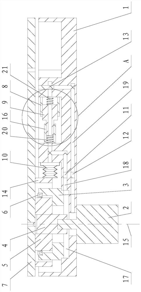
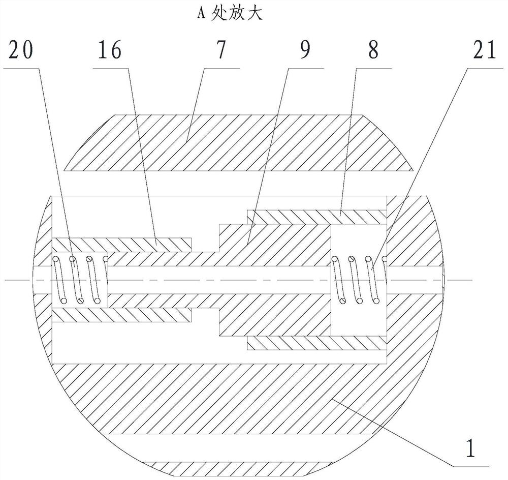
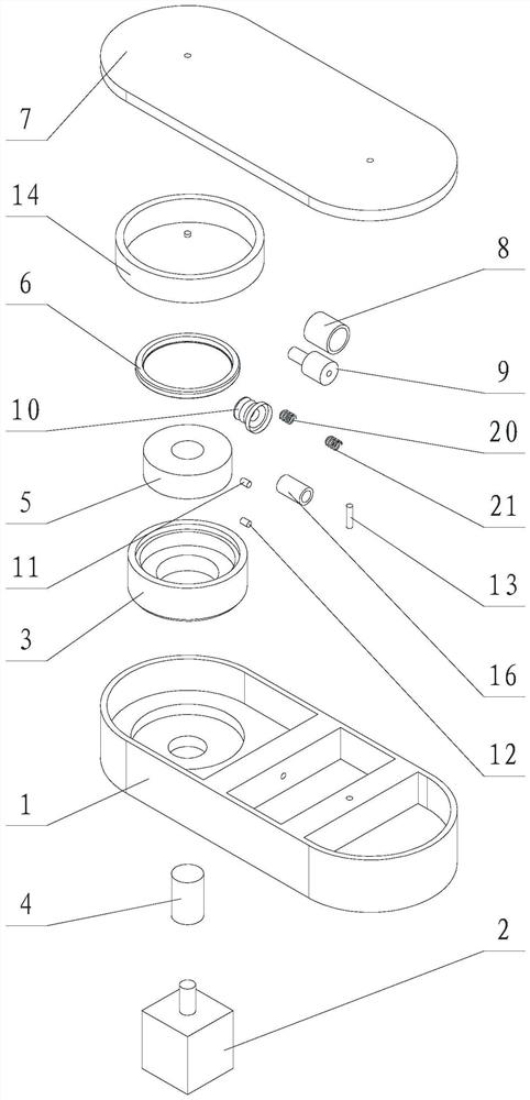
[0020] Such as Figure 1~3 As shown, the present invention includes a boom 1, a small arm 7, a motor 2 and a reducer housing 3 respectively accommodated in the boom 1, a reducer input gear shaft 4, a reducer output shaft 5, an inertial double-headed piston mechanism, Oil outlet one-way valve 11, oil return one-way valve 12 and filter element 13, in which the motor 2 is statically sealed and fixedly connected to the boom 1, the output end penetrates into the boom 1, and the gear shaft 4 is input through the reducer and the output of the reducer One end of the shaft 5 is connected, one end of the reducer casing 3 is statically sealed and fixedly connected in the boom 1, and the other end is connected with the output shaft 5 of the reducer through a rotating dynamic seal 6, and the other end of the reducer casing 3 is connected to the reducer The machine input ...


PUM


Abstract

The invention relates to an active cam type lubricating self-cleaning mechanism. The motor is statically sealed and connected to the boom, the output end is connected to one end of the output shaft of the reducer through the input gear shaft of the reducer, and one end of the reducer casing is installed on the large arm with static seal. In the arm, the other end is connected to the output shaft of the reducer in a sealed rotation, and the other end of the output shaft of the reducer is connected to the forearm in a static seal; the two ends of the inertial double-headed piston form a moving pair with the large and small cylinders respectively and are connected in a sealed manner. There is a reducer inner cavity filled with grease. The reducer inner cavity is connected to the inside of the small cylinder through the oil passage A, and the inside of the large cylinder is connected to the reducer inner cavity through the oil passage B. In the oil passage A There is an oil outlet check valve that can only flow to the small cylinder, and an oil return check valve that can only flow to the inner cavity of the reducer in the oil passage B; a filter element is installed in the oil passage B near the large cylinder. The invention can stabilize the internal pressure of the robot joints, prevent oil leakage, reduce energy efficiency, and have better energy-saving and environmental protection effects.

Description

technical field [0001] The invention relates to a robot joint cleaning lubrication system in the cleaning industry, in particular to an active cam type lubrication self-cleaning mechanism. Background technique [0002] The joints of the robot contain motors and reducers. For routine applications, there may be oil leakage or leakage for many reasons. However, it is absolutely not allowed to be used in the clean industry. If the reducer is in a relatively closed state, a certain amount of friction will be generated between each pair of gears in the reducer, and this friction will emit a certain amount of heat; The extension of time will directly lead to a certain degree of temperature increase in the reducer box; and the volume of the reducer box remains unchanged, so the pressure in the reducer box will also increase accordingly, and the lubricating oil in the box will After splashing, it will be sprinkled on the inner wall of the gear box. Since the oil is relatively perm...

Claims


Application Information

Patent Timeline
Patent Type & Authority Patents(China)
IPC IPC(8): B25J19/00F16H57/04
Inventor 朱维金孙宝龙王凤利陈立博王金涛任哲锋马子良李野
Owner SHENYANG SIASUN ROBOT & AUTOMATION
Why Eureka
Try Eureka