A Lubrication Mechanism Based on Variable Volume

A technology of variable volume mechanism and lubricating mechanism, which is applied in gear lubrication/cooling, manipulators, manufacturing tools, etc., and can solve problems such as robot penetration of grease

Active Publication Date: 2021-09-10
SHENYANG SIASUN ROBOT & AUTOMATION
View PDF0 Cites 0 Cited by
  • Summary
  • Abstract
  • Description
  • Claims
  • Application Information

AI Technical Summary

Problems solved by technology

[0004] In order to solve the problem of grease penetration by robots in the cleaning industry, the purpose of the present invention is to provide a lubrication mechanism based on variable volume

Method used


Image

  • A Lubrication Mechanism Based on Variable Volume
  • A Lubrication Mechanism Based on Variable Volume
  • A Lubrication Mechanism Based on Variable Volume

Examples


Embodiment Construction

[0019] The present invention will be described in further detail below in conjunction with the accompanying drawings.

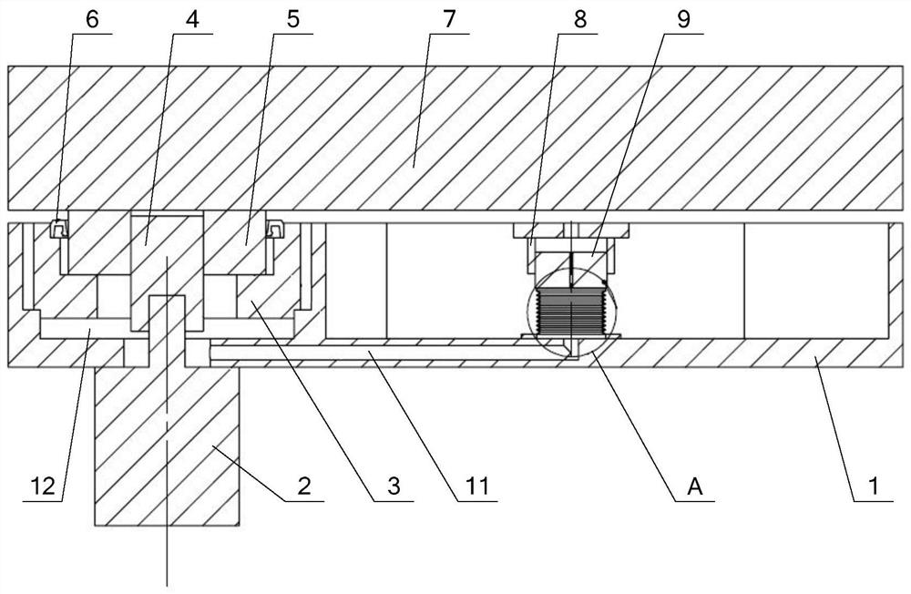
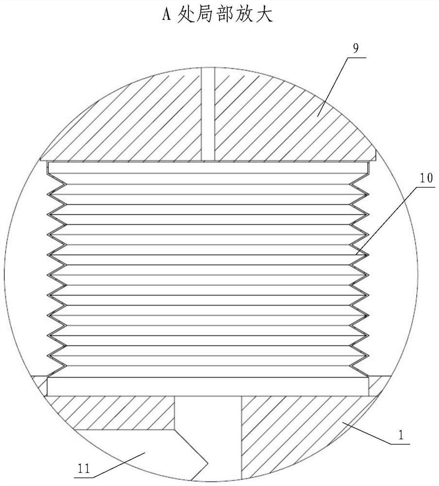
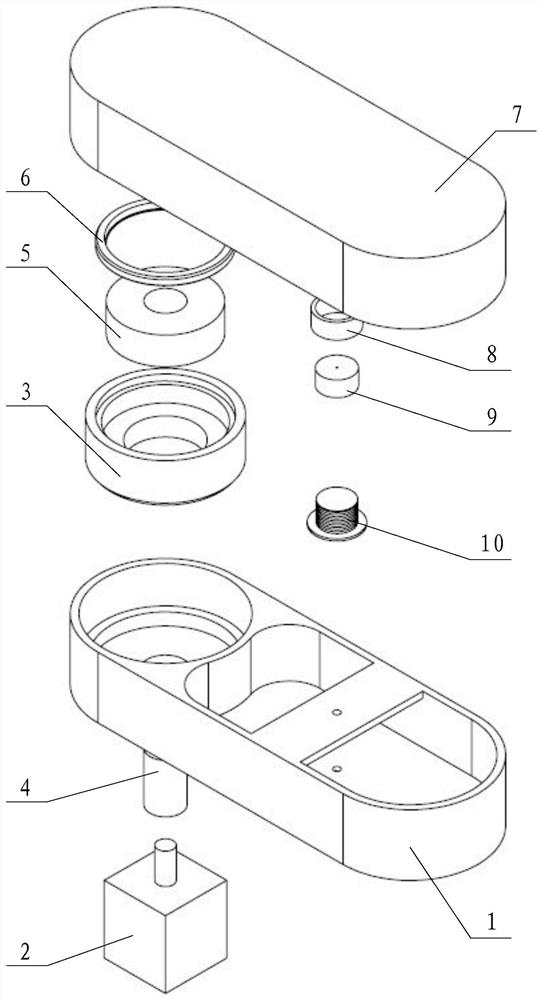
[0020] Such as Figure 1~3 As shown, the present invention includes a boom 1, a small arm 7, a motor 2, and a reducer casing 3, a reducer input gear shaft 4, a reducer output shaft 5 and an elastic variable volume mechanism 10 respectively housed in the boom 1. The boom 1 is relatively fixed, the motor 2 is statically sealed and fixedly connected to the boom 1, the output end penetrates into the boom 1, and is connected to one end of the reducer output shaft 5 through the reducer input gear shaft 4, and the reducer casing 3 One end is statically sealed and fixedly connected in the boom 1, and the other end is sealed and rotated with the reducer output shaft 5 through the rotating dynamic seal 6. The other end of the reducer casing 3 is connected with the reducer input gear shaft 4 and the reducer output shaft 5. And the rotary dynamic seal 6 forms the transm...


PUM


Abstract

The invention relates to a cleaning and lubricating system for robot joints in the cleaning industry, in particular to a lubrication mechanism based on variable volume. One end of the reducer shell is installed in the boom with a static seal, the other end is connected with the output shaft of the reducer and the other end is connected with the forearm static seal; the boom is provided with an oil circuit and a reducer The inner cavity of the reducer and the inner cavity of the reducer are connected with the inside of the elastic variable volume mechanism installed in the boom through the oil circuit, and the constant pressure in the inner cavity of the reducer is maintained through the expansion or reduction of the volume of the elastic variable volume mechanism. The internal pressure of the joints of the robot of the invention is stable, no oil leakage or oil leakage, the failure probability of the rotating dynamic seal can be reduced, and the rotating dynamic seal with a slightly loose rotation can also be rotated in the design stage, so that the joint rotation resistance of the robot is small and energy efficiency is reduced. , the effect of energy saving and environmental protection is better and more significant.

Description

technical field [0001] The invention relates to a cleaning lubricating system for robot joints in the cleaning industry, in particular to a lubricating mechanism based on variable volume. Background technique [0002] The joints of the robot contain motors and reducers. For routine applications, there may be oil leakage or leakage for many reasons. However, it is absolutely not allowed to be used in the clean industry. If the reducer is in a relatively closed state, a certain amount of friction will be generated between each pair of gears in the reducer, and this friction will emit a certain amount of heat; The extension of time will directly lead to a certain degree of temperature increase in the reducer box; and the volume of the reducer box remains unchanged, so the pressure in the reducer box will also increase accordingly, and the lubricating oil in the box will After splashing, it will be sprinkled on the inner wall of the gear box. Since the oil is relatively perme...

Claims


Application Information

Patent Timeline
Patent Type & Authority Patents(China)
IPC IPC(8): F16H57/04B25J19/00
Inventor 朱维金王凤利陈立博孙宝龙刘亚超王金涛周明远周斌
Owner SHENYANG SIASUN ROBOT & AUTOMATION
Why Eureka
Try Eureka