Three-phase motor braking method and device
A technology of three-phase motor and braking device, which is applied in the direction of reduction device of AC motor, electric motor/converter plug, etc., can solve the problems of short service life, high cost and complex mechanical structure of brake pads.
- Summary
- Abstract
- Description
- Claims
- Application Information
AI Technical Summary
Problems solved by technology
Method used
Image

Examples
Embodiment 1
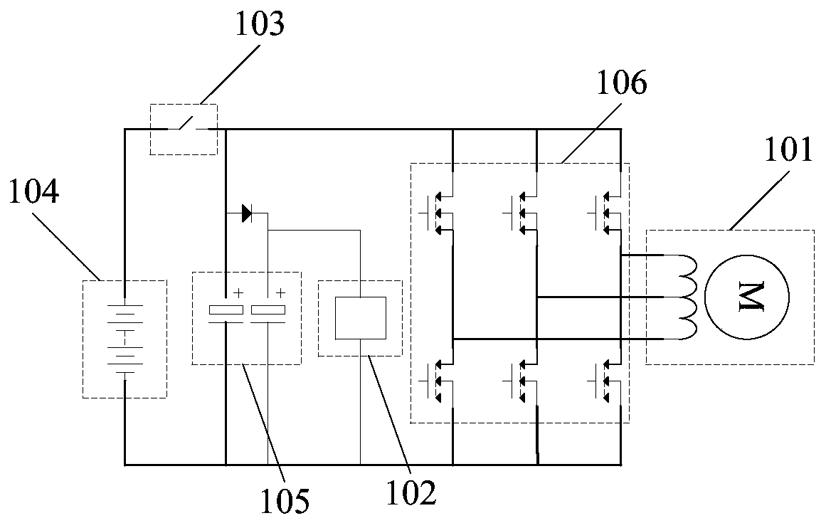
[0027] figure 1 The schematic diagram of the circuit structure of the three-phase motor braking device provided by the embodiment of the present invention is shown. For ease of description, only the parts related to the present invention are shown.
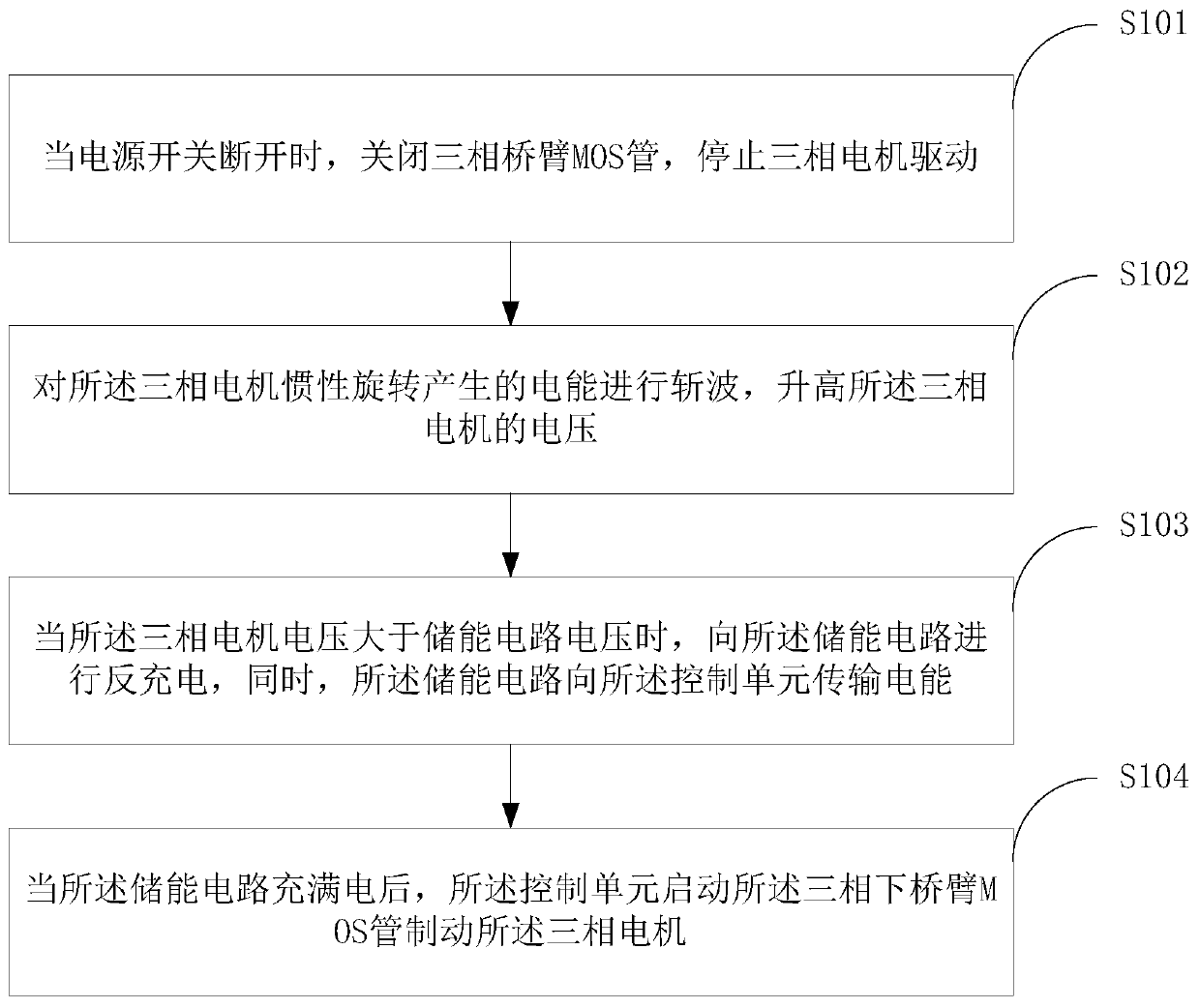
[0028] The three-phase motor braking device includes a three-phase DC brushless three-phase motor 101, a control unit 102, a main switch 103 and a battery pack 104, an energy storage circuit 105 and a three-phase full bridge drive circuit 106, of which three-phase DC brushless three-phase The motor 101 is connected to the three-phase full-bridge drive circuit 106, one end of the two ends of the energy storage circuit 105 is connected to the battery pack 104, and the other end is connected to the main switch 103. When the main power switch 103 in the control unit 102 is turned off, the electric energy generated by the inertial rotation of the three-phase brushless DC three-phase motor 101 is chopped to increase the voltage value of the...
Embodiment 2
[0031] figure 2 It shows a schematic flowchart of a three-phase motor braking method provided by an embodiment of the present invention. For ease of description, only the parts related to the present invention are shown.
[0032] In step S101, when the power switch is turned off, the three-phase bridge arm MOS transistor is turned off, and the three-phase motor drive is stopped.
[0033] In the embodiment of the present invention, the motor includes a DC motor and an AC motor. The DC motor can be divided into a DC brushless motor and a brushed DC motor. The DC brushless motor has a simple structure, reliable operation, and convenient maintenance. Series advantages, and the advantages of DC motors such as high operating efficiency, no excitation loss and good speed regulation performance, so DC brushless motors are applied in various fields.
[0034] In the embodiment of the present invention, a three-phase motor means that when the three-phase stator windings of the motor (each phas...
Embodiment 3
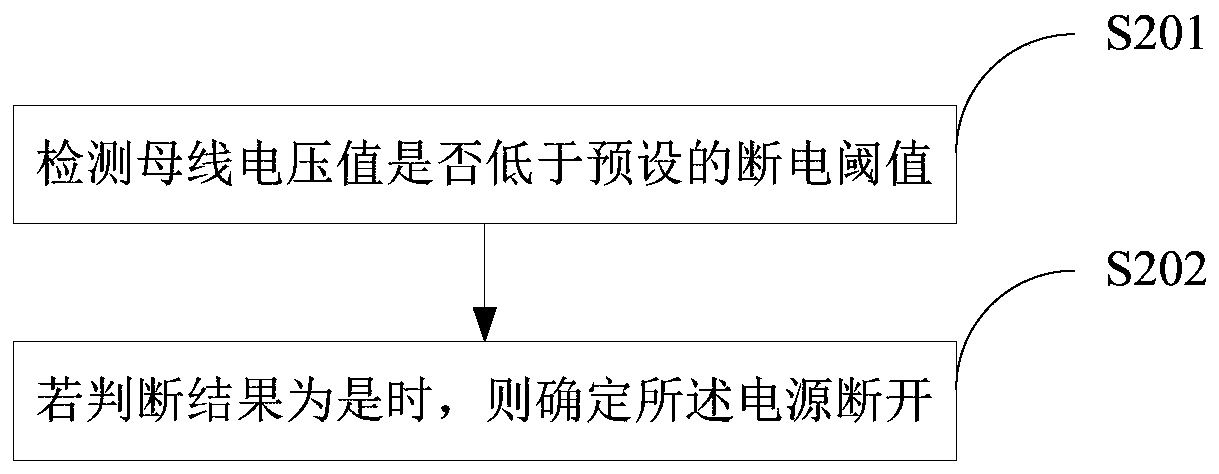
[0044] As an improvement of the second embodiment of the present invention, image 3 It shows a schematic flow chart of a method for determining power disconnection provided by an embodiment of the present invention. For ease of description, only parts related to the present invention are shown.
[0045] In step S101, step S201 and step S202 are included.
[0046] In step S201, it is detected whether the bus voltage value is lower than a preset power-off threshold.
[0047] In the embodiment of the present invention, the power-off threshold can be set according to the experience of the technician.
[0048] In step S202, if the judgment result is yes, it is determined that the power supply is off.
[0049] In the embodiment of the present invention, by detecting whether the bus voltage of the control board is lower than a preset threshold, it is determined whether the switch is disconnected, so as to determine the disconnection of the power source, avoiding misidentification, and improvi...
PUM
 Abstract
Description
Claims
Application Information
 - R&D
- Intellectual Property
- Life Sciences
- Materials
- Tech Scout
- Unparalleled Data Quality
- Higher Quality Content
- 60% Fewer Hallucinations
Browse by: Latest US Patents, China's latest patents, Technical Efficacy Thesaurus, Application Domain, Technology Topic, Popular Technical Reports.
© 2025 PatSnap. All rights reserved.Legal|Privacy policy|Modern Slavery Act Transparency Statement|Sitemap|About US| Contact US: help@patsnap.com