
Brake freewheeling circuit, brake braking system and brake freewheeling control method

A freewheeling circuit and open circuit control technology, applied in the direction of speed reducer components, etc., can solve the problems of extending the brake release time, increasing the resistance value of the freewheeling resistance, reducing the release time, etc., to solve the noise and release time, slow down the current Falling speed, the effect of increasing the current falling speed

Active Publication Date: 2021-03-02
HITACHI ELEVATOR CHINA
View PDF11 Cites 0 Cited by
  • Summary
  • Abstract
  • Description
  • Claims
  • Application Information

AI Technical Summary

Problems solved by technology

During the implementation process, the inventor found that reducing the release noise of the brake and reducing the release time are contradictory without changing the mechanical structure of the brake: in order to reduce the release noise of the brake, the resistance value of the freewheeling resistor should be reduced, resulting in The current of the brake coil decreases slowly, prolonging the release time of the brake, which further leads to an increase in the braking distance of the motor equipment of the brake
On the contrary, in order to reduce the release time and the braking distance of the motor equipment, the resistance value of the freewheeling resistor is increased to make the current of the brake coil drop faster, resulting in louder brake release noise
However, in the face of the aforementioned contradictions, there is still no effective solution. That is to say, the traditional brake control method has the problem of not being able to reduce the maximum noise of the brake release and shorten the release time.

Method used


Image

  • Brake freewheeling circuit, brake braking system and brake freewheeling control method
  • Brake freewheeling circuit, brake braking system and brake freewheeling control method
  • Brake freewheeling circuit, brake braking system and brake freewheeling control method

Examples


Embodiment Construction

[0042] In order to make the purpose, technical solutions and advantages of the present application more clearly understood, the present application will be described in further detail below with reference to the accompanying drawings and embodiments. It should be understood that the specific embodiments described herein are only used to explain the present application, but not to limit the present application. It should be noted that when an element is considered to be "connected" to another element, it may be directly connected to and integrated with the other element, or an intervening element may also be present, that is, it may also be indirectly connected to the other element .

[0043] Unless otherwise defined, all technical and scientific terms used herein have the same meaning as commonly understood by one of ordinary skill in the technical field to which this application belongs. The terms used herein in the specification of the application are for the purpose of des...


PUM


Abstract

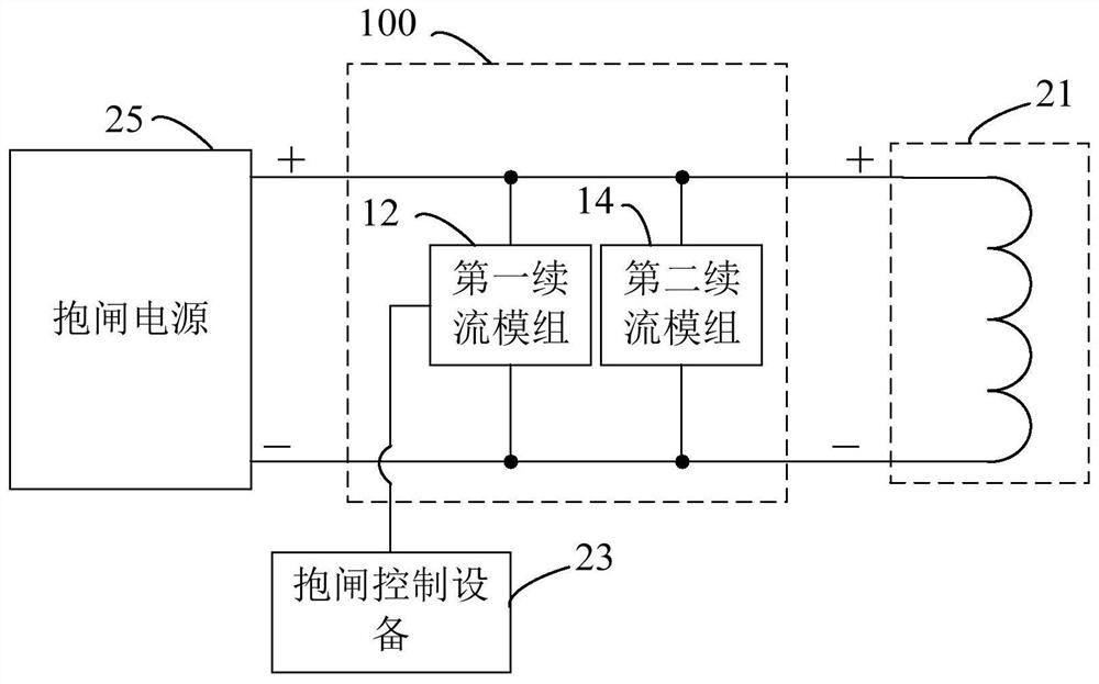
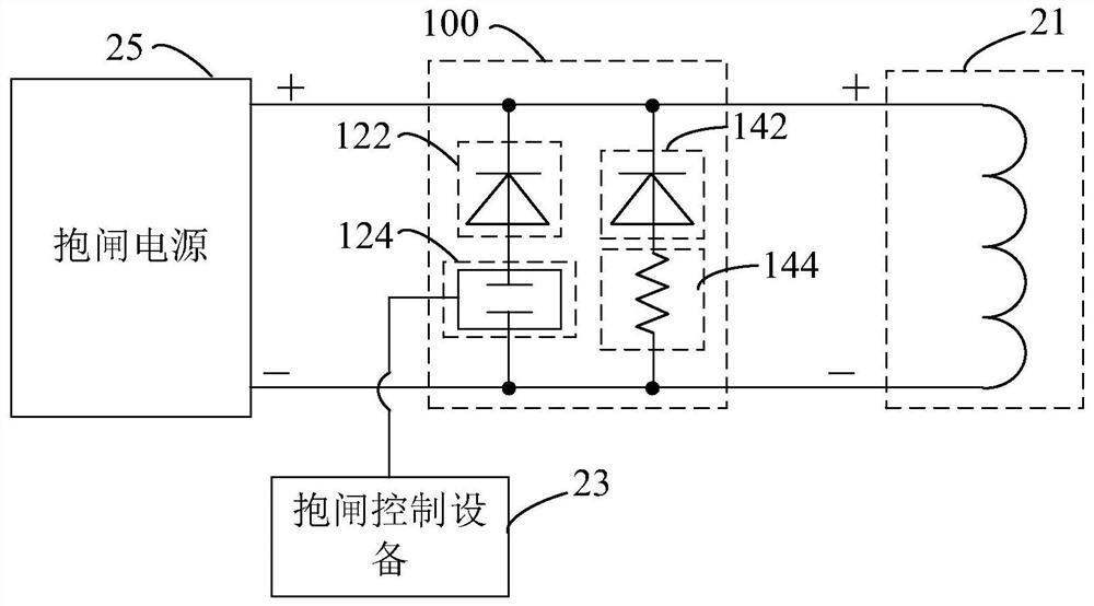
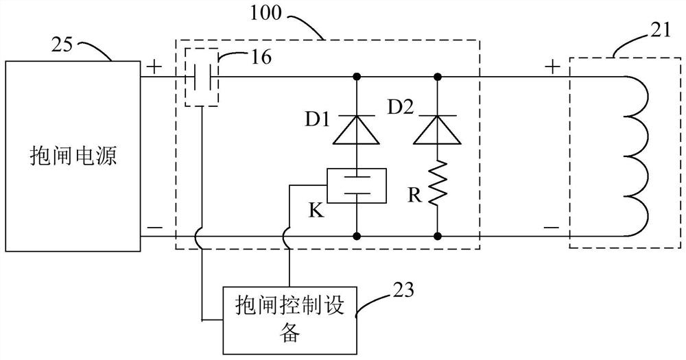
The invention relates to a brake closing follow current circuit, a brake closing system and a brake closing follow current control method. The brake closing follow current circuit comprises a first follow current module and a second follow current module, which are connected in parallel. The equivalent resistance value of the first follow current module is smaller than that of the second follow current module. The positive ends of the first follow current module and the second follow current module are connected to the positive end of the brake closing coil. The negative ends of the first follow current module and the second follow current module are connected to the negative end of the brake closing coil. The first follow current module is connected when receiving a closing control signalwhen a brake starts to be released, performs the current following of the brake closing coil and is disconnected when receiving an open circuit control signal after a brake shoe impacts a wheel surface of a main unit. The second follow current module is used for carrying out current following of the brake closing coil after the first follow current module is disconnected. Through the design of the double follow current loops, the resistance of the follow current loops can be adjusted in the brake release process, the maximum noise of brake release is effectively reduced, and the release timeis effectively shortened.

Description

technical field [0001] The present application relates to the technical field of motor braking, and in particular, to a holding brake freewheeling circuit, a holding brake braking system and a holding brake freewheeling control method. Background technique [0002] Different brakes are different in terms of mechanical structure, working current, coil inductance and coil resistance. During the implementation process, the inventor found that reducing the brake release noise and reducing the release time are contradictory without changing the mechanical structure of the brake: in order to reduce the brake release noise, reduce the resistance of the freewheeling resistor, resulting in The current of the brake coil decreases slowly, prolonging the release time of the brake, which further leads to an increase in the stopping distance of the motor equipment braked by the brake. On the contrary, in order to reduce the release time and the braking distance of the motor equipment, in...

Claims


Application Information

Patent Timeline
Patent Type & Authority Patents(China)
IPC IPC(8): H02P3/02
Inventor 郭志海刘俊斌赖志鹏郭威
Owner HITACHI ELEVATOR CHINA
Learn More