
Cooling system and vehicle drive system for drive system

A technology of cooling system and drive system, applied in cooling/ventilation device, gear lubrication/cooling, connection with control/drive circuit, etc., can solve problems such as leaks, and achieve the effect of saving components and reducing costs

Pending Publication Date: 2019-05-24
ZF FRIEDRICHSHAFEN AG
View PDF8 Cites 0 Cited by
  • Summary
  • Abstract
  • Description
  • Claims
  • Application Information

AI Technical Summary

Problems solved by technology

As a result, there is a high risk of leaks

Method used


Image

  • Cooling system and vehicle drive system for drive system

Examples


Embodiment Construction

[0028] specific implementation plan

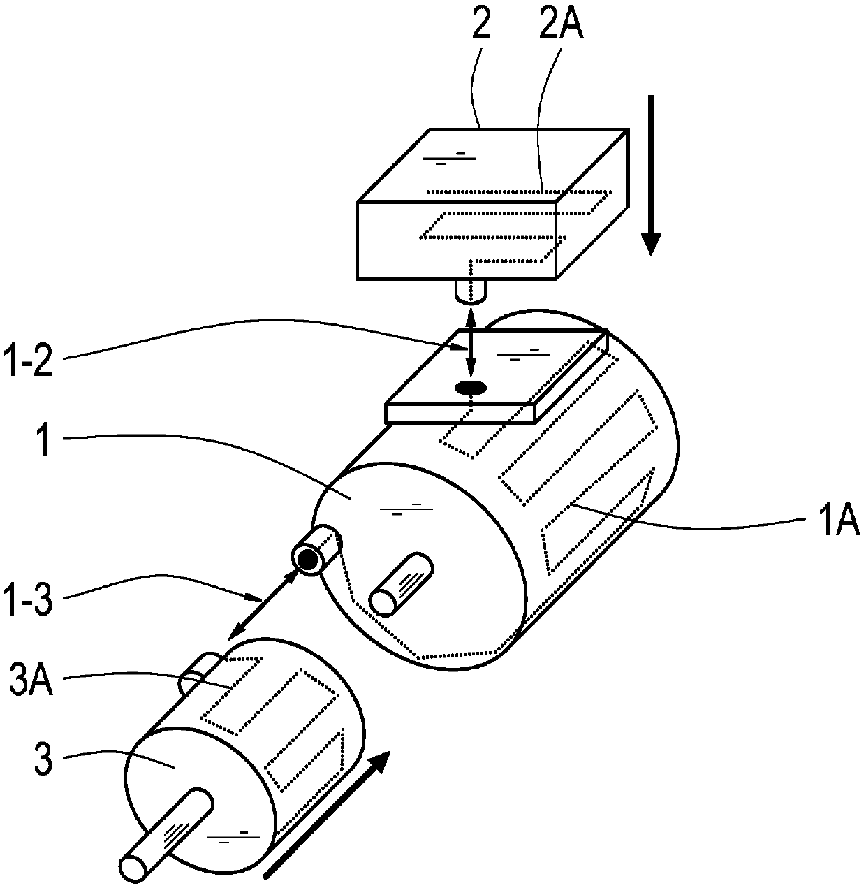
[0029] The drive system has a motor 1 and an inverter 2 for driving the motor 1 . Furthermore, the drive system has a transmission 3 for converting the torque of the electric machine 1 . The inverter 2 and the transmission 3 are designed for arrangement on an electric machine (see thick arrow). That is, the inverter 2 and the transmission 3 are fastened to the motor 1 . The transmission 3 is then fastened, for example, on the end side of the electric machine 1 and the inverter is fastened, for example, on the radial side of the electric machine 1, as figure 1 shown.

[0030] The motor 1 has a motor cooling structure 1A for guiding a cooling medium to flow through to cool the motor 1 . The inverter 2 has an inverter cooling structure 2A for guiding a cooling medium to flow through to cool the inverter 2 . Optionally, the transmission also has a transmission cooling structure 3A for guiding a cooling medium to flow through to cool the t...


PUM


Abstract

The present invention relates to a cooling system and a vehicle drive system for a drive system. The vehicle drive system includes such a cooling system. Here, a motor (1) and functional units (2, 3)arranged on the motor are provided, as well as a motor cooling structure (1A) for guiding the cooling medium to cool the motor (1) and cooling functional unit cooling structures (2A, 3A) for guiding the cooling medium to cool the functional units (2, 3). The motor cooling structure (1A) and the functional unit cooling structure (2A, 3A) have unique common interfaces (1-2, 1-3), which can be used in these cooling structures (1A, 2A; 1A, 3A) through a unique common interface to exchange the cooling medium.

Description

technical field [0001] The invention relates to a cooling system for a drive system having an electric machine and having a functional unit arranged on the electric machine, as well as a vehicle drive system having such a cooling system. Background technique [0002] Motor vehicles usually have at least two coolant circuits. The consumer and the generator are cooled in series or in parallel with the first cooling medium circuit. Typically the traction battery is cooled using a secondary circuit. The electric drive system (ie at least the electric machine and the associated inverter) is usually cooled in series in the first circuit. The inverter is flow-through as the first component in order to ensure a minimum flow-through temperature. Afterwards, the electric drive machine of the drive system and possibly the transmission behind the electric motor are cooled. [0003] In the automotive sector, the integration of the electric machine, the associated inverter and the tra...

Claims


Application Information

Patent Timeline
Patent Type & Authority Applications(China)
IPC IPC(8): H02K9/00H02M7/00F16H57/04
CPCF16H57/04H02M7/00H02M7/003H02K7/006H02K7/116F16H57/0476H02K11/33H02K5/203
Inventor 亚历山大·比尔克凯文·亨布格尔戴维·齐尔克曼纽尔·施瓦布塞巴斯蒂安·阿派尔安东·比歇尔迈尔迈克尔·里斯
Owner ZF FRIEDRICHSHAFEN AG
Learn More