High-density cross connecting cabinet

An optical cable transfer box, high-density technology, applied in the direction of fiber mechanical structure, etc., can solve the problems of small space for optical cable transfer box, messy optical fiber routing, inconvenient management, etc., and achieve the effect of clear wiring, flexible operation and convenience

Pending Publication Date: 2019-05-24
宁波隆兴电信设备制造有限公司
View PDF1 Cites 0 Cited by
  • Summary
  • Abstract
  • Description
  • Claims
  • Application Information

AI Technical Summary

Problems solved by technology

The traditional optical cable transfer box mainly includes a fusion integration unit and an optical splitter unit. It has the following defects in use: 1. The optical fiber fusion disk in the fusion integration unit occupies a large space in the optical cable transfer box, and then The use of space in the optical cable transfer box is small, and the mixed optical fibers in the transfer box with a small use of space are not only more messy, the wiring pressure is greater, and it is not easy to manage

Method used


Image

  • High-density cross connecting cabinet
  • High-density cross connecting cabinet
  • High-density cross connecting cabinet

Examples


Embodiment Construction

[0028] The present invention will be further described in detail below in conjunction with the accompanying drawings and embodiments.

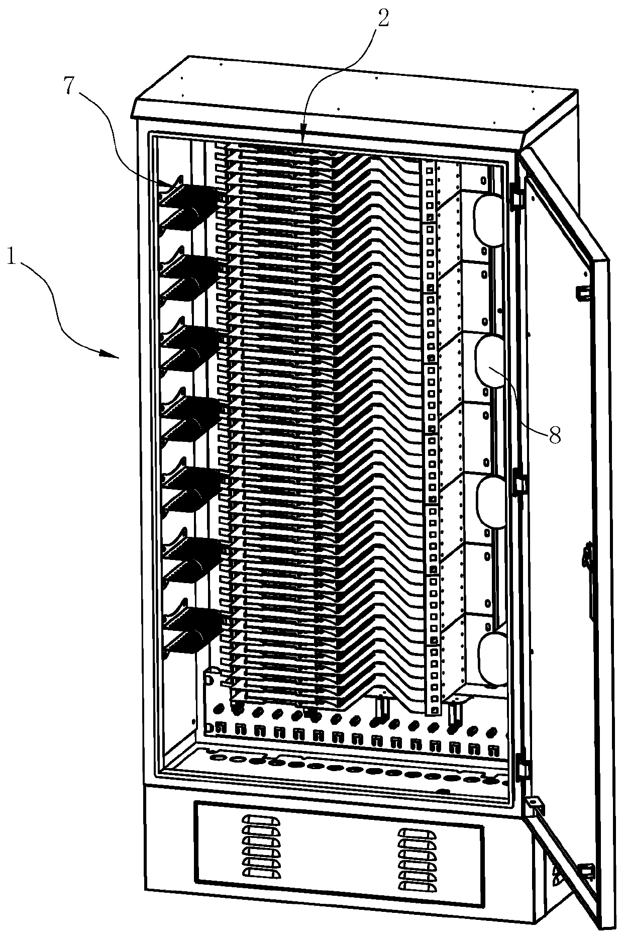
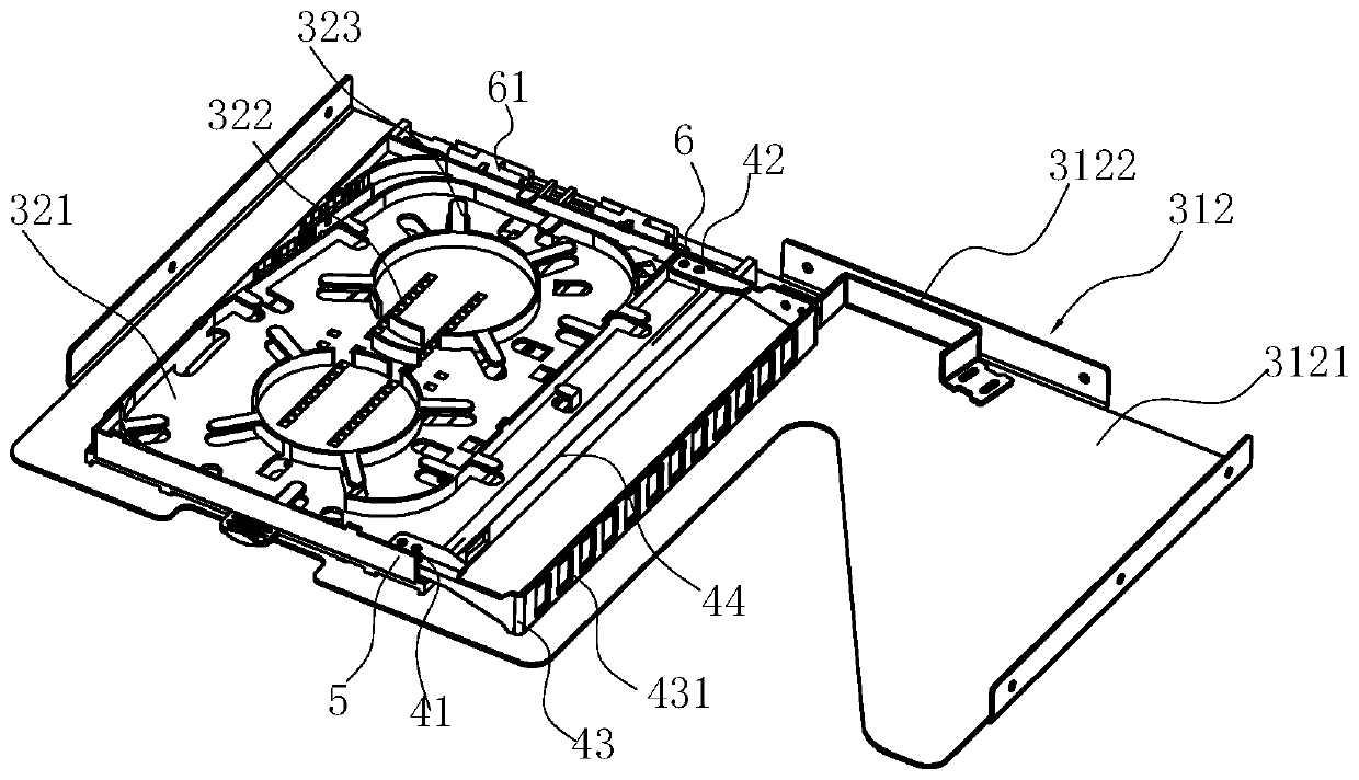
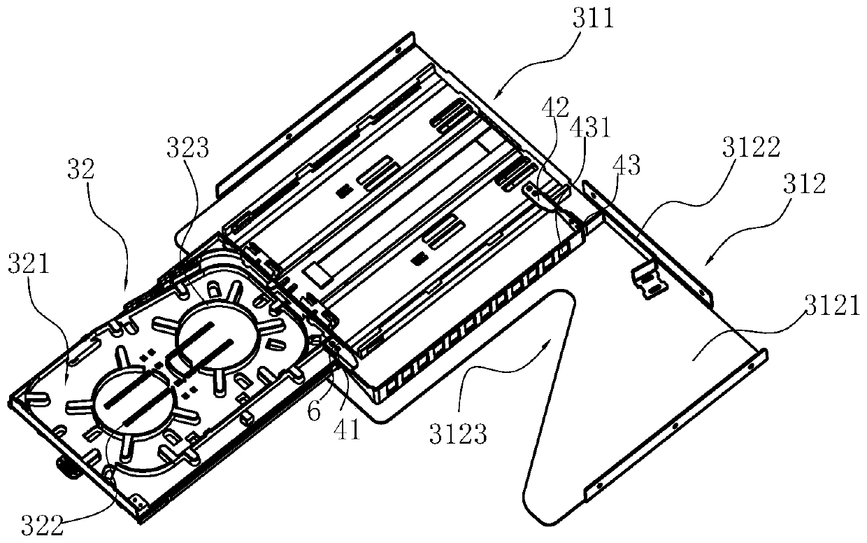
[0029] like Figure 1-9 Shown is the preferred embodiment of the present invention. The high-density fiber optic cable splicing box in this embodiment includes a frame 1, and the frame 1 includes at least two stacked optical fiber splicing tray unit boxes 2, and the optical cable splicing tray unit box 2 includes a mounting frame 21 and a And the fiber splicing tray 3 inserted on the installation frame 21 at intervals in turn, the fiber splicing tray 3 includes a tray 31 and a base 32 that can slide relative to the tray 31, wherein the base 32 includes a wall surrounded by the side wall of the base 32 And the formed concave cavity 321, the fusion splice tray 322 arranged in the central part of the cavity 321, wherein the fusion splice tray 322 includes a fusion seat with 24 cores or 36 core card slots 3221, and is arranged on the outer periph...


PUM


Abstract

The invention relates to a high-density cross connecting cabinet. The high-density cross connecting cabinet comprises a frame and at least two stacked optical cable fiber melting plate unit boxes andis characterized in that each optical cable fiber melting plate unit box comprises a mounting rack and fiber melting plates which are sequentially inserted onto the mounting rack at intervals from topto bottom, each fiber melting plate comprises a support plate and a base which can slide relative to the support plate, each base comprises a concave cavity formed by the surrounding lateral wall ofthe base, a welding plate and a distribution board, and each support plate comprises a guide plate and a bottom plate. Compared with the prior art, the high-density cross connecting cabinet has the advantages that the fiber melting plates in the high-density cross connecting cabinet have support plates and bases which can slide relative to each other, staff can pull the bases at will during fibermelting, the support plates are provided with fiber winding seats allowing the tail fibers of tail fiber adapters to wind, the support plates are partially provided with notches facing the fiber winding seats, and the tail fibers after welding are directly guided to the fiber winding seats through the notches.

Description

technical field [0001] The invention relates to an optical cable transfer box, in particular to a high-density optical cable transfer box. Background technique [0002] The optical cable transfer box is the interface device between the backbone optical cable and the distribution optical cable in the optical fiber access network. It is mainly used for the connection, distribution and scheduling of outdoor optical cables; the optical cable transfer box can fix, weld, and For jumping, protection and management, the optical cable transfer box is a transfer device that provides optical cable termination and jumper for backbone layer optical cables and distribution layer optical cables. The fiber optic cable transfer box is one of the important supporting equipment for realizing fiber to the curb (FTTC), fiber to the building (FTTB) and fiber to the user (FTTH). The traditional optical cable transfer box mainly includes a fusion integration unit and an optical splitter unit. It h...

Claims


Application Information

Patent Timeline
Patent Type & Authority Applications(China)
IPC IPC(8): G02B6/44
Inventor 陈正龙岺伊纳段维进邱丽慧杨灵芝
Owner 宁波隆兴电信设备制造有限公司
Why Eureka
Try Eureka