Eureka AIR delivers breakthrough ideas for toughest innovation challenges, trusted by R&D personnel around the world.

Floating-type wave energy conversion device

A conversion device and wave energy technology, applied in the direction of electromechanical devices, ocean energy power generation, mechanical energy control, etc., can solve the problems of fragile power generation efficiency, high energy conversion efficiency, low production cost, etc., to improve stability and service life, The effect of increasing the total amount of energy and saving the cost of protection

Active Publication Date: 2019-05-24
HOHAI UNIV
View PDF6 Cites 1 Cited by
  • Summary
  • Abstract
  • Description
  • Claims
  • Application Information

AI Technical Summary

Problems solved by technology

The nodding duck type ideally has high power generation efficiency, but it is only suitable for ideal sea conditions and regular waves, and the multi-moving parts are exposed to seawater for a long time, the reliability of the device is poor, and it is easy to be damaged. Low energy conversion efficiency but difficult maintenance, easy to damage and unstable power generation efficiency, only suitable for large-scale power generation devices placed on breakwaters; oscillating float type, simple construction, high efficiency in absorbing wave energy but receiving too much It is easily damaged after impact, and the total power generation is not large, so it is only suitable for providing energy for some lighthouses and buoys

Method used


Image

  • Floating-type wave energy conversion device
  • Floating-type wave energy conversion device
  • Floating-type wave energy conversion device

Examples


Embodiment Construction

[0027] In order to make the technical means, creative features, goals and effects achieved by the present invention easy to understand, the present invention will be further described below in conjunction with specific embodiments.

[0028] It should be noted that, in the description of the present invention, the terms "front", "rear", "left", "right", "upper", "lower", "inner", "outer" and the like indicate orientations or positions The relationship is based on the orientation or positional relationship shown in the drawings, and is only for the convenience of describing the present invention and does not require that the present invention must be constructed and operated in a specific orientation, and thus should not be construed as a limitation of the present invention. The terms "front", "rear", "left", "right", "upper" and "lower" used in the description of the present invention refer to the directions in the drawings, and the terms "inner" and "outer" refer to is the dir...


PUM


Abstract

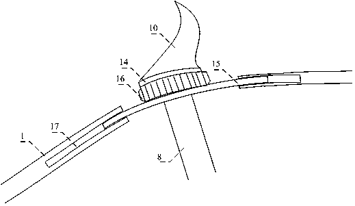
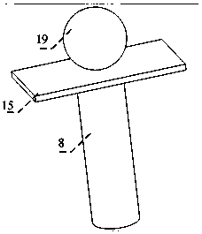
The invention discloses a floating-type wave energy conversion device, which comprises a hollow shell, a wave-approach assembly for collecting wave energy, and a conversion assembly for converting thewave energy into electrical energy. The wave-approach assembly comprises wave-approach plates arranged outside the shell, and wave-approach plate idler wheels connected with the wave-approach plates,a moving track is formed in the shell, and the wave-approach plate idler wheels are driven by the wave-approach plates to roll along the moving track; the conversion assembly comprises generators, asupporting sleeve rod, connecting rods and positioning gears, wherein the generators, the supporting sleeve rod, the connecting rods and the positioning gears are arranged in the shell, and the positioning gears are used for positioning the connecting rods; the positioning gears are in transmission connection with rotating shafts of the generators; a sliding piece slidably connected with the supporting sleeve rod is arranged on the supporting sleeve rod; one ends of the connecting rods are hinged to the sliding piece, and the other ends of the connecting rods are hinged to the wave-approach plate idler wheels; the connecting rods are further provided with racks engaged with the positioning gears; and the wave-approach plates are impacted by waves to drive the connecting rods to move through the wave-approach plate idler wheels, and the racks arranged on the connecting rods drive the positioning gears to rotate, and thus drive the generators to generate electricity.

Description

technical field [0001] The invention relates to the technical field of marine renewable energy engineering, in particular to a floating wave energy conversion device. Background technique: [0002] In recent years, with the rapid development of economic construction in coastal areas, coastal industries such as tourism and marine aquaculture have gradually emerged, and the requirements for wave-proof energy storage in coastal waters have become higher and higher. According to statistics and calculations of wave observation data, the theoretical average power of wave energy resources in my country's coastline has reached more than 12 million kilowatts, and the global economically valuable wave energy extraction has reached 100-1000 million kW. As a big energy country, my country's demand for energy is increasing year by year. While using a large amount of non-renewable resources, it is actively looking for renewable new energy that can be replaced. With its clean, pollution-fr...

Claims


Application Information

Patent Timeline
IPC IPC(8): F03B13/16F03B11/02H02K7/18
CPCY02E10/20Y02E10/30
Inventor 张颖男杨雪儿刘畅陆发靖彭伟
Owner HOHAI UNIV
Why Eureka
Eureka Blog
Learn More