Air mixing damper arrangement

一种混合风门、风门的技术,应用在空气处理设备、运输和包装、加热/冷却设备等方向,能够解决多空间、占用等问题

Inactive Publication Date: 2019-05-24
MAHLE INT GMBH
View PDF5 Cites 5 Cited by
  • Summary
  • Abstract
  • Description
  • Claims
  • Application Information

AI Technical Summary

Problems solved by technology

In addition, such dampers are usually located at different locations within the air conditioner housing, causing such dampers to take up more space

Method used


Image

  • Air mixing damper arrangement
  • Air mixing damper arrangement
  • Air mixing damper arrangement

Examples


Embodiment Construction

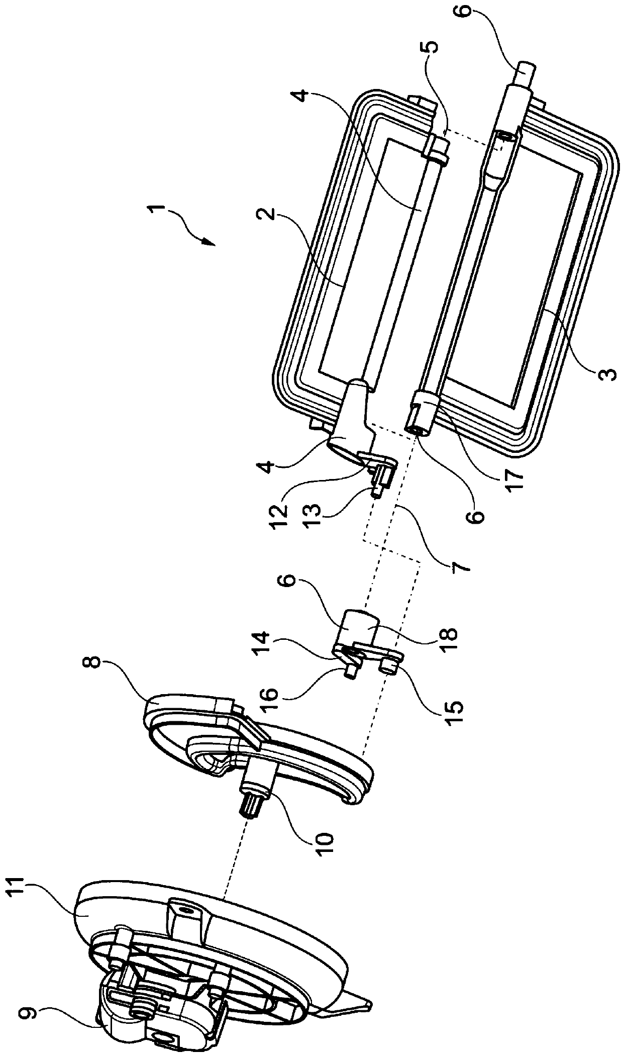
[0091] figure 1 A perspective exploded view of the air mixing damper device 1 of the air-conditioning device 100 in particular for a motor vehicle is shown. The air conditioner 100 has a cooling air flow channel and a heating air flow channel, wherein a cooling device such as an evaporator is located in the cooling air flow channel to cool the air. In addition, a heating device such as a heater core is located in the heating air flow passage to heat the air. The other drawings show details of the air mixing damper device 1.

[0092] The air mixing damper device 1 has a first cooling air damper 2, called a first damper, for controlling the cooling air in the cooling air flow channel, and a second heating air damper 3, called a second damper, for Control the heating air in the heating air flow channel. When the first damper 2 is completely closed and the second damper 3 is completely opened, the heated air is delivered to the mixing chamber of the air conditioner 100. In the cas...


PUM


Abstract

An air mixing damper arrangement having a first cooled air damper damping cooled air in a cooled air flow path and a second heated air damper damping heated air in a heated air flow path, wherein thefirst damper has a first shaft having a first center of rotation and the second damper has a second shaft having a second center of rotation, wherein the first center of rotation and the second centerof rotation are substantially identically aligned. The first damper and the second damper are individually rotatable about their respective center of rotation, wherein the first damper and the seconddamper are both actuated by a cam plate, the first damper has a lever having a pin having a top level shape and a bottom level shape, the second damper has a lever having a first pin and a second pin. The shape of the first pin matches with the bottom layer of the pin of the first damper. The cam plate is provided with a first groove having a first top layer and a second bottom layer, and a second groove having layer levels. The top layer of the pin of the first damper can move in the top layer of the first groove, and the bottom layer of the pin of the first damper can move in the bottom layer of the first groove. The first pin of the second damper can move in the bottom layer of the first groove, and the second pin of the second damper can move in the second groove.

Description

Technical field [0001] The invention relates to an air mixing damper device, especially an air conditioner for motor vehicles. Background technique [0002] The air conditioner usually includes a housing in which at least one air flow channel is provided. In addition, this air conditioner includes a blower unit for supplying air into the housing of the air conditioner so that the air flows through at least one air flow channel. An evaporator and a heater core are usually arranged in the air flow channel. The evaporator cools the air flow through the evaporator, and the heater core generally heats the air flow through the heater core. [0003] In order to control the amount of heating and / or cooling air and cooling and heating air mixture, an air mixing damper device is provided, which controls the amount of cooling air passing through the evaporator and entering the mixing chamber, and controlling the amount of cooling air passing through the heater core and entering the mixing c...

Claims


Application Information

Patent Timeline
Patent Type & Authority Applications(China)
IPC IPC(8): B60H1/00
CPCB60H1/00678B60H1/00857
Inventor 菲利普·索科洛夫斯基马丁·斯图科史蒂夫·M·齐林斯基
Owner MAHLE INT GMBH
Why Eureka
Try Eureka