
Water treatment equipment control box

A technology for water treatment equipment and control cabinets, which is applied to casings/cabinets/drawer components, electrical equipment casings/cabinets/drawers, electrical components, etc., which can solve the problems of high wiring difficulty and heavy workload, and achieve Convenient on-site installation, reduced wiring workload, and convenient circuit maintenance

Pending Publication Date: 2019-05-21
洛阳金邦博环保科技有限公司
View PDF0 Cites 4 Cited by
  • Summary
  • Abstract
  • Description
  • Claims
  • Application Information

AI Technical Summary

Problems solved by technology

[0004] The purpose of the present invention is to provide a water treatment equipment control box in order to solve the above problems, so as to solve the technical problems of high difficulty in field wiring and heavy workload of the water treatment equipment control device in the prior art

Method used


Image

  • Water treatment equipment control box
  • Water treatment equipment control box
  • Water treatment equipment control box

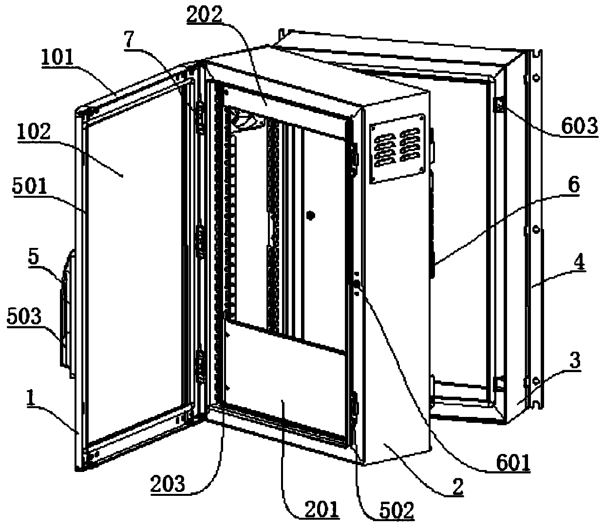
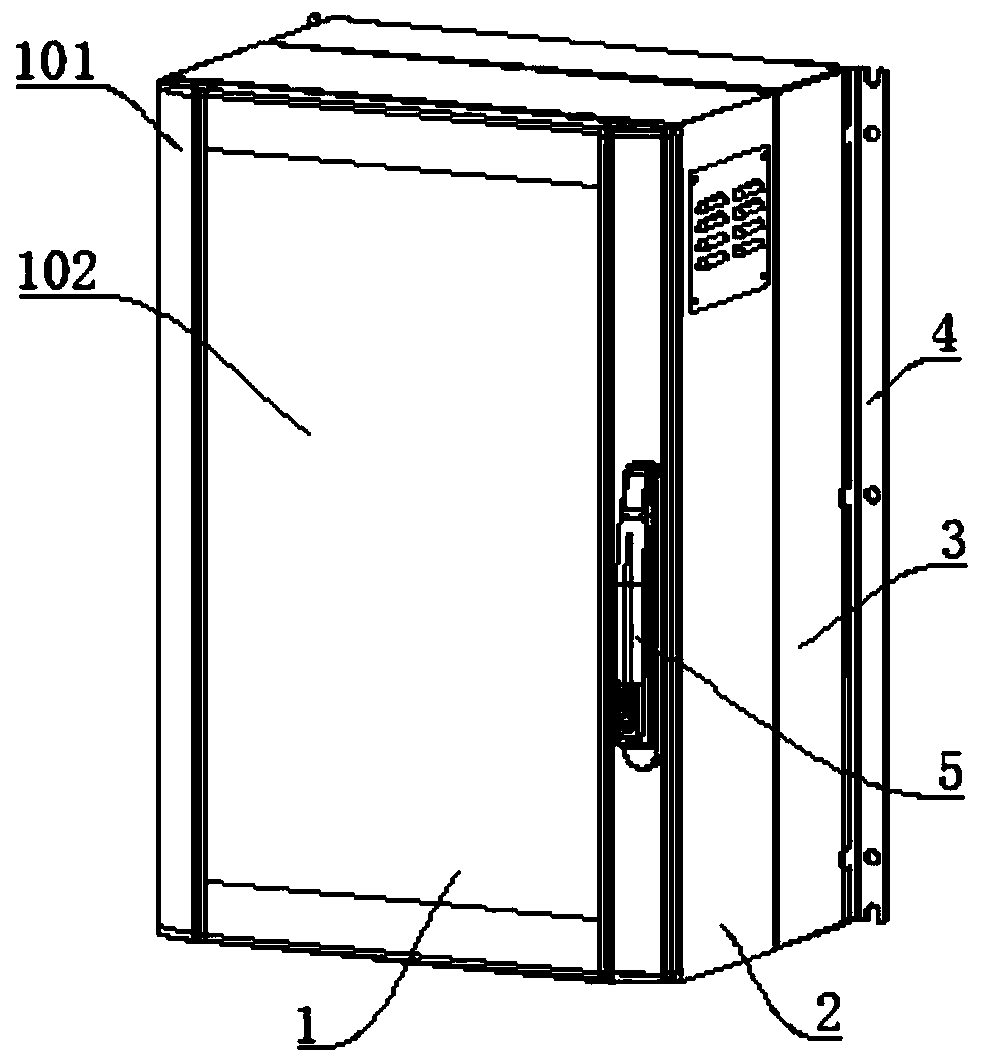
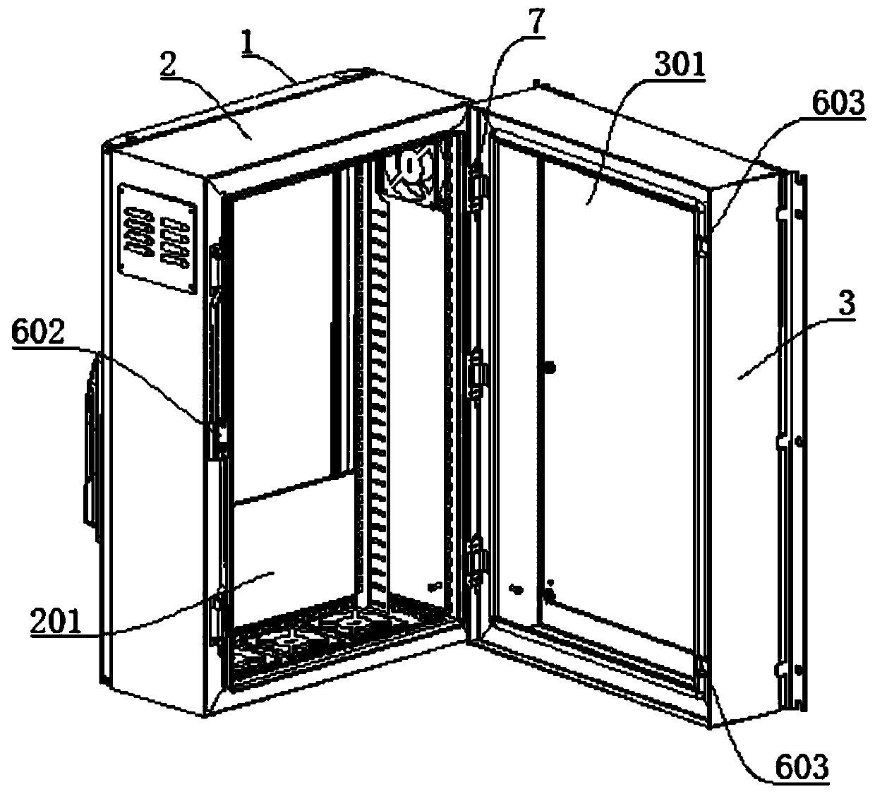
Examples


Embodiment Construction

[0023] In order to make the purpose, technical solution and advantages of the present invention clearer, the technical solution of the present invention will be described in detail below. Apparently, the described embodiments are only some of the embodiments of the present invention, but not all of them. Based on the embodiments of the present invention, all other implementations obtained by persons of ordinary skill in the art without making creative efforts fall within the protection scope of the present invention.

[0024] see Figure 1-3 As shown, the present invention provides a water treatment equipment control box, including a weak current box, a strong current box and a door panel, the door panel includes a frame and a glass window, and the glass window is embedded around the inside of the frame, so that , so that when the door panel is in the locked state, the detection data of the detection instrument on the weak current box can be directly viewed through the glass ...


PUM


Abstract

The invention discloses a water treatment equipment control box, comprising a weak current box body, a strong current box body and a door plate. The door plate comprises a frame and a glass window. Four sides of the glass window are inlaid at inner sides of the frame. The door plate is mounted at a front side of the weak current box body through utilization of an anti-drop hinge. The strong current box body is mounted at a rear side of the weak current box body through utilization of the anti-drop hinge. An opening of the strong current box body faces one side of the weak current box body. A handle lock locked with the weak current box body is set at a free end of the door plate. A rack locking mechanism locked with the strong current box body is set at the free end of the weak current boxbody. The control box has the beneficial effects that the box body is set into a three-layer structure, so a strong current part and a weak current part are integrated into a case body, field installation is facilitated and wiring workload of a field worker can be greatly reduced; and the strong current part and the weak current part are independently set in two box bodies, so circuit maintenanceof the two parts is greatly facilitated.

Description

technical field [0001] The invention relates to the field of electromagnetic water treatment, in particular to a water treatment equipment control cabinet. Background technique [0002] The water treatment equipment control device is the control part of the electronic antiscaling system. The control part usually includes a strong current part for adjusting voltage and current and a weak current part for detecting various data. [0003] The applicant found that there are at least the following technical problems in the prior art: the existing strong current control part and the weak current control part need to be installed in different control boxes, and not only the two control boxes need to be installed and fixed on site, but also due to The weak current control box needs to be led from the strong current control box, and the detection signal needs to be fed back to the strong current control box. Therefore, after the two boxes are installed on site, secondary wiring is re...

Claims


Application Information

Patent Timeline
IPC IPC(8): H05K5/00H05K5/02
Inventor 薄祥兵
Owner 洛阳金邦博环保科技有限公司
Learn More