
A high-speed motor rotor core manufacturing process

A rotor iron core and manufacturing process technology, applied in the field of manufacturing process of high-speed motor rotor iron core, can solve the problems of unevenness and verticality error rotor iron core, etc. The effect of pressure coefficient and dimensional stability

Active Publication Date: 2021-01-22
SANMENXIA HONGXIN NONFERROUS METALS
View PDF10 Cites 0 Cited by
  • Summary
  • Abstract
  • Description
  • Claims
  • Application Information

AI Technical Summary

Problems solved by technology

[0004] In view of the above problems, the purpose of the present invention is to provide a rotor that can solve the unevenness and verticality errors caused by the unequal height of the silicon steel punching sheet due to the thickness difference, and the unevenness and verticality error caused by the protruding part of the stacked riveting structure punching sheet and the concave hole error. Core manufacturing process

Method used


Image

  • A high-speed motor rotor core manufacturing process
  • A high-speed motor rotor core manufacturing process

Examples


Embodiment Construction

[0025] The implementation of the present invention will be illustrated by specific specific examples below, and those skilled in the art can easily understand other advantages and effects of the present invention from the contents disclosed in this specification.

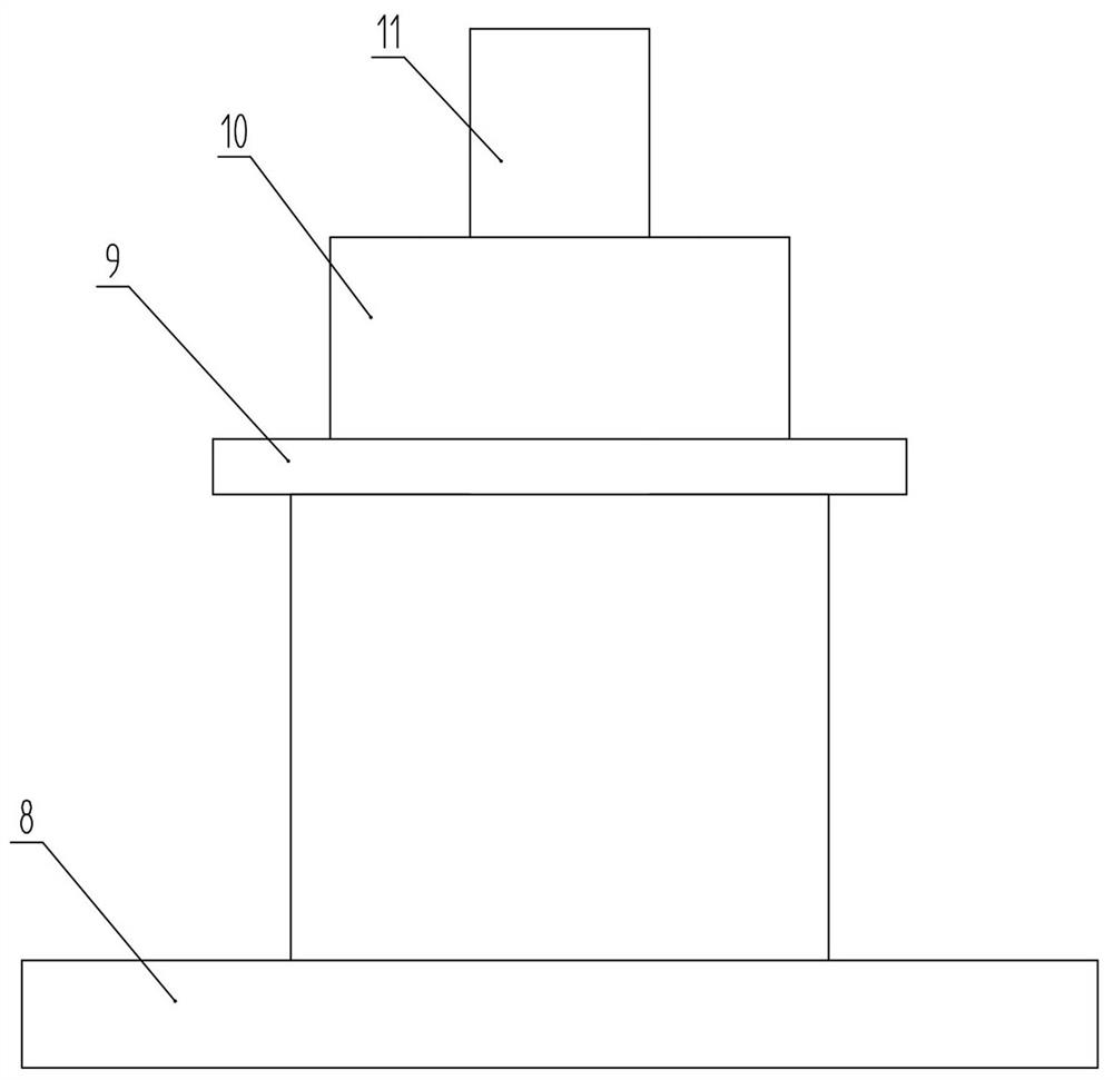
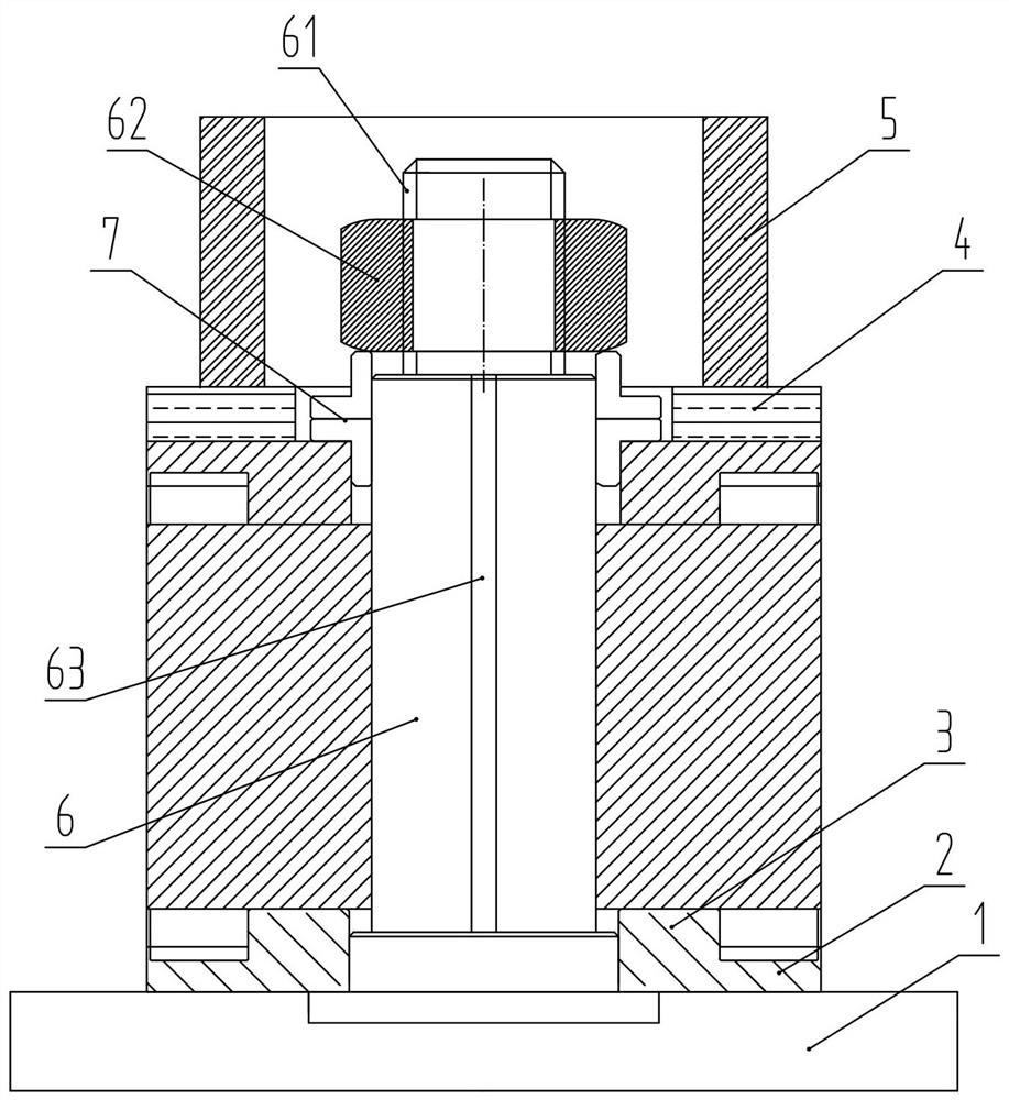
[0026] see figure 1 . The structures, proportions, sizes, etc. shown in the drawings attached to this specification are only used to cooperate with the content disclosed in the specification, for those who are familiar with this technology to understand and read, and are not used to limit the conditions for the implementation of the present invention. Therefore, there is no technical substantive meaning, and any modification of structure, change of proportional relationship or adjustment of size shall still fall within the scope of the disclosure of the present invention without affecting the functions and objectives of the present invention. within the scope of technical content. At the same time, terms such as "...


PUM


Abstract

The invention discloses a high-speed motor rotor core manufacturing process, comprising the following steps: S1, providing a hydraulic machine, a laminating tool, a universal punching sheet and a folding and riveting punching sheet which is formed by punching on a punching machine; S2, lamination of layered iron cores: the to-be-pressed rotor core is divided into a plurality of layered iron coresaccording to the height and the like, and then the layered iron cores are placed on the laminating tool; S3, lamination of the iron cores: a first layered iron core is firstly arranged, then, a secondlayered iron core is placed, and the layered iron cores are horizontally rotated by 180 degrees to complete the lamination of the iron cores; S4, assembling of a welding tool: the welding tool is assembled on a platform, then, an end ring and the iron cores are sequentially placed, and nuts are used for locking; and S5, the end ring and a guide bar are welded, so that the rotor core is manufactured. The layered iron cores are laminated and are adjusted under the pressure of the hydraulic machine, so that the height error of the rotor core is reduced; the layered iron cores are still finishedin a stamping die, and manufacturing of the high-speed motor core can be realized in a high-efficiency and high-quality mode.

Description

technical field [0001] The invention relates to the technical field of motor manufacturing technology, in particular to a manufacturing technology of a rotor core of a high-speed motor. Background technique [0002] For the operation of the motor and other aspects, the iron core manufacturing process is an effective part of the motor, and has a great impact on its performance in all aspects. We divide the manufacturing process of the iron core in the motor into two parts, one is the manufacture of punching sheets, and the other is the manufacture of iron core pressing. For the structure of high-speed motor punching, there are general structure and stacked riveting structure. The punching process and mold structure are basically the same. Small high-speed motors mostly use re-punching process schemes. The mold structure adopts a continuous mold. After stamping, the common structure punches must be laminated in a single piece, and the lamination tooling is used to complete th...

Claims


Application Information

Patent Timeline
Patent Type & Authority Patents(China)
IPC IPC(8): H02K15/02
Inventor 邱希赞邱保安王兆麒
Owner SANMENXIA HONGXIN NONFERROUS METALS
Learn More