
System for securing a clock movement in a watch case

A movement and watch case technology, applied in the system field of components, can solve problems such as undesired removal of fixtures, plastic deformation of fixtures, etc.

Pending Publication Date: 2019-05-21
ROLEX SA
View PDF7 Cites 0 Cited by
  • Summary
  • Abstract
  • Description
  • Claims
  • Application Information

AI Technical Summary

Problems solved by technology

[0006] However, such a scheme can be problematic
In fact, there is a risk of plastic deformation of the fixture during assembly and / or under impact
This may result in an undesired loss of contact between the movement and the middle, or an undesired risk of removing the clamp

Method used


Image

  • System for securing a clock movement in a watch case
  • System for securing a clock movement in a watch case
  • System for securing a clock movement in a watch case

Examples


Embodiment Construction

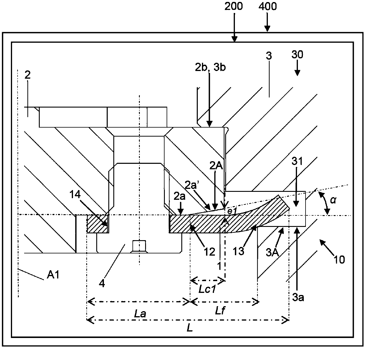
[0054] Refer below image 3 and Figure 4 A first embodiment of the clock 400 is described. For example, a clock is a watch, especially a watch. The timepiece comprises a watch case or case 30 comprising a middle 3 . Case 30 houses movement 2 of the timepiece. The movement can be a mechanical movement or an electronic movement.

[0055] The movement 2 of the timepiece and / or the element 3 of the case and / or the case 30 may form or form part of a clock unit 200 comprising elements 3 for securing the movement 2 of the timepiece to the case 30 the system 10 or help the system 10. For example, an element of a watch case could be a middle or enlarged ring.

[0056] A system 10 for securing a movement 2 of a timepiece to an element 3 of a case comprises:

[0057] - at least one gripper 1 , in particular at least two grippers, preferably three grippers or four grippers, intended to come into contact firstly with the movement and secondly with elements of the case, and

[0058...


PUM

PropertyMeasurementUnit
lengthaaaaaaaaaa
thicknessaaaaaaaaaa

Abstract

The system (10) for fixing a timepiece movement (2) to a watch case (30) element (3) comprises at least one clamp (1), in particular at least two clamps, preferably three clamps or four clamps, whichis intended to come into contact firstly with the movement and secondly with the watch case element, the at least one clamp being made of a superelastic alloy and / or of a shape memory alloy, particularly of a nickel-titanium alloy such as Nitinol.

Description

technical field [0001] The invention relates to a system for securing a movement of a timepiece to an element of a watch case. The invention also relates to a clock unit comprising such a system. The invention also relates to a clock comprising such a system or such a unit. Finally, the invention relates to a method of operating such a system or such a unit or such a clock. Background technique [0002] Typically, two or three case clamps are used to assemble or secure the movement of the clock within the case, especially the middle. [0003] When assembling the movement within the watch case, each case clamp is inserted into a cutout formed on the inner periphery of the middle portion, and then fixed to the movement by a fixing device. [0004] This notch can in particular be shaped so that the clamp can generate a suitable prestress, which can press the movement against the middle of the case to meet predetermined criteria. For example, one criterion could be for a spe...

Claims


Application Information

Patent Timeline
Patent Type & Authority Applications(China)
IPC IPC(8): G04B37/04
CPCG04B37/052G04B43/002
Inventor 伯努瓦·朱诺雅姆·赖兹内
Owner ROLEX SA
Learn More