Pyranometer and photometric device
A technology of intensity meter and light, which is applied in measuring devices, photometry using electric radiation detectors, photometry, etc., can solve problems such as sensor errors and achieve the effect of reducing COS errors
- Summary
- Abstract
- Description
- Claims
- Application Information
AI Technical Summary
Problems solved by technology
Method used
Image
Examples
Embodiment approach 1
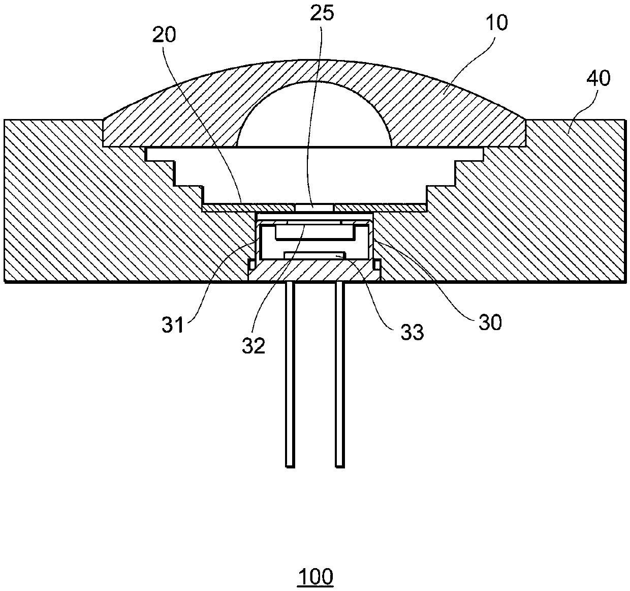
[0050] figure 1 It is a side cross-sectional view showing an example of a schematic configuration of a pyranometer 100 according to an embodiment of the present invention. The pyranometer 100 is, for example, a pyranometer defined and classified according to the ISO9060 standard. Additionally, a spectroradiometer may also be included in the pyranometer. like figure 1 As shown, the pyranometer 100 includes a condenser lens (first lens) 10 , a light shielding ring 20 , a sensor 30 , and a housing 40 .
[0051] The condensing lens 10 is a lens for condensing incident light and guiding the light to the sensor 30 , for example, a concave meniscus lens can be used. A light-shielding ring 20 is provided between the condenser lens 10 and the sensor 30 .
[0052] The light-shielding ring 20 is a member having a light-transmitting region 25 in the center. The light-shielding ring 20 is composed of one or more parts (workpieces), preferably has a predetermined or higher strength and...
Embodiment approach 2
[0059] Figure 4 It is a side sectional view showing an example of a schematic configuration of a pyranometer 101 according to an embodiment of the present invention. and figure 1 The same symbols indicate the same or similar structures. Such as Figure 4 As shown, the pyranometer 101 includes not only the light-shielding ring 20 but also light-shielding rings 21 and 22 . Like the light-shielding ring 20 , the light-shielding rings 21 and 22 have a light-transmitting region 25 at the center, and the center of the light-transmitting region 25 is located on the optical axis of the condensing lens 10 .
[0060] The three light-shielding rings 20 to 22 are configured such that the area becomes smaller as they are closer to the sensor 30 , that is, the area of the light-transmitting region 25 becomes smaller in the order of the light-shielding ring 22 , the light-shielding ring 21 , and the light-shielding ring 20 .
[0061] Figure 5 It is a diagram schematically showing li...
Embodiment approach 3
[0065] Figure 7 It is a side cross-sectional view showing an example of a schematic configuration of a pyranometer 102 according to an embodiment of the present invention. and figure 1 , Figure 4 The same symbols indicate the same or similar structures. Such as Figure 7 As shown, the pyranometer 102 has two light shielding rings 20 , 21 . In addition, the pyranometer 102 includes a condenser lens 11 between the condenser lens 10 and the light shielding ring 21 .
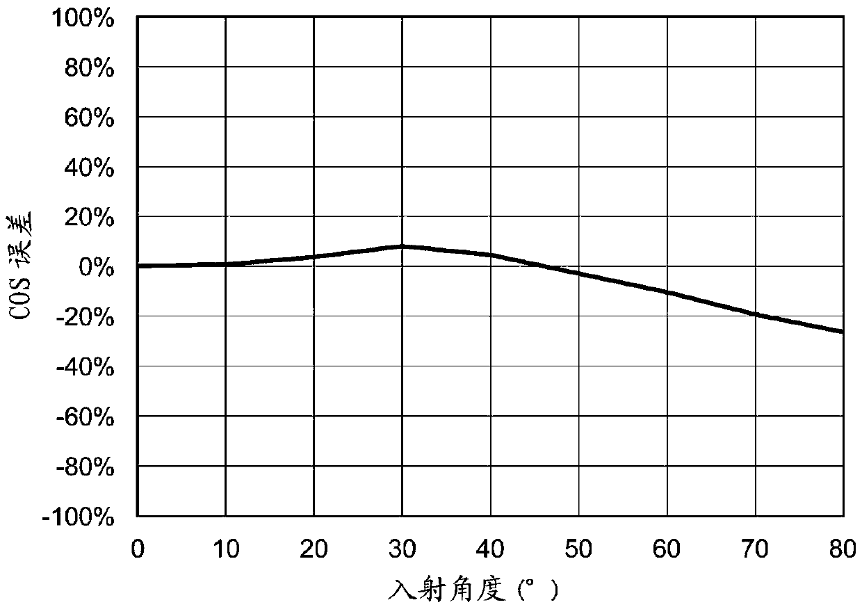
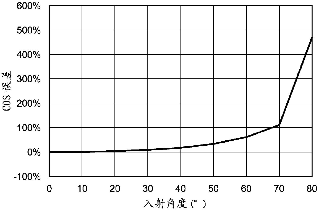
[0066] Figure 8 It is a graph showing an example of the relationship between the incident angle measured by the pyranometer 102 and the COS error. Figure 8 The horizontal axis in the center is the incident angle (°), and the vertical axis is the COS error (%). and image 3 It can be seen from the comparison of the graphs of the pyranometer 102 that the COS error of the pyranometer 102 is significantly improved compared with the pyranometer of the comparative example.
[0067] As described above, accordi...
PUM
 Abstract
Description
Claims
Application Information
 - R&D
- Intellectual Property
- Life Sciences
- Materials
- Tech Scout
- Unparalleled Data Quality
- Higher Quality Content
- 60% Fewer Hallucinations
Browse by: Latest US Patents, China's latest patents, Technical Efficacy Thesaurus, Application Domain, Technology Topic, Popular Technical Reports.
© 2025 PatSnap. All rights reserved.Legal|Privacy policy|Modern Slavery Act Transparency Statement|Sitemap|About US| Contact US: help@patsnap.com


