Robot vision inertial point linear feature positioning method and device

A technology of robot vision and feature location, applied in the field of robot navigation, which can solve the problems of difficult repeated detection of feature points, error matching rate of feature points, changes in perspective and climate change, etc.

Active Publication Date: 2019-05-14
ZHEJIANG UNIV
View PDF7 Cites 11 Cited by
  • Summary
  • Abstract
  • Description
  • Claims
  • Application Information

AI Technical Summary

Problems solved by technology

The traditional visual positioning method based on feature point matching for camera fundamental matrix estimation is easily affected by problems such as viewing angle changes, dynamic occlusion, ambient lighting, and climate change, resulting in problems such as difficult repeated detection of feature points and high error matching rate of detected feature points.

Method used


Image

  • Robot vision inertial point linear feature positioning method and device
  • Robot vision inertial point linear feature positioning method and device
  • Robot vision inertial point linear feature positioning method and device

Examples


Embodiment Construction

[0063] In the following, the technical solutions of the present invention will be further described in conjunction with the drawings and specific implementation methods.

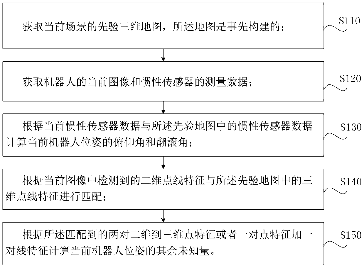
[0064] figure 1 It is a schematic flow chart of the robot visual inertial point and line feature positioning method of the present invention. The present invention discloses a robot visual inertia point line feature positioning method, which includes the following steps:

[0065] 1. Obtain a priori three-dimensional map of the current scene, the map is constructed in advance, and the map is required to include the measurement data of the acceleration of gravity in the map coordinate system, which is generally measured by an inertial sensor, specifically when determining the map coordinate system At the same time, the acceleration data measured by the inertial sensor is saved; the three-dimensional map also includes three-dimensional point-line features, so that it can be matched with the two-dimensional poin...


PUM


Abstract

The invention discloses a robot vision inertial point linear feature positioning method and device. The robot vision inertial point linear feature positioning method comprises the steps that a priorithree-dimensional map of a current scene and measuring data of an inertial sensor are obtained, and the priori three-dimensional map is constructed in advance and comprises the three-dimensional pointlinear feature; and a current image of a robot and measuring data of an inertial sensor are obtained. According to the robot vision inertial point linear feature positioning method and device, fusionof multiple sensors is utilized, advantage information of all the sensors are fully exerted in an algorithm, and the effect of improving the position accuracy and robustness is finally achieved.

Description

technical field [0001] The invention relates to robot navigation technology, in particular to a method and device for locating robot visual inertial point and line features. Background technique [0002] At present, more and more different types of robots appear in all aspects of production and life. For warehousing logistics, inspection and monitoring and other fields, the work requires robots to be able to achieve long-term stable operation in a relatively fixed environment, and to achieve accurate self-positioning. The production cost of the visual sensor is low, and the amount of information obtained is large, and the related positioning methods are widely studied and applied. The traditional visual positioning method based on feature point matching for camera fundamental matrix estimation is easily affected by problems such as viewing angle changes, dynamic occlusion, ambient lighting, and climate change, resulting in difficult repeated detection of feature points and ...

Claims


Application Information

Patent Timeline
IPC IPC(8): G01C21/20G01C21/16
Inventor 王越焦艳梅熊蓉
Owner ZHEJIANG UNIV
Why Eureka
Try Eureka