
Piezoelectric ultrasonic transducer and working method thereof

A piezoelectric ultrasonic and transducer technology, applied in the direction of fluid using vibration, etc., can solve the problems of weak sensitive signal of piezoelectric ultrasonic transducer, unable to be popularized and applied on a large scale, and unable to be arrayed on a large scale, so as to simplify the process and steps, increased sensitivity, performance-enhancing effects

Pending Publication Date: 2019-05-14
CHONGQING UNIV
View PDF0 Cites 1 Cited by
  • Summary
  • Abstract
  • Description
  • Claims
  • Application Information

AI Technical Summary

Problems solved by technology

[0003] At present, piezoelectric ultrasonic transducers have problems such as weak sensitive signals, poor manufacturability, and inability to be arrayed on a large scale.
In the detection of physical quantities, the sensitive signal (sensitivity) is an important characterization quantity, especially for micro-integrated chips, the weak sensitive signal will make the chip cannot be used normally, and thus cannot be widely used.

Method used


Image

  • Piezoelectric ultrasonic transducer and working method thereof
  • Piezoelectric ultrasonic transducer and working method thereof
  • Piezoelectric ultrasonic transducer and working method thereof

Examples


Embodiment 1

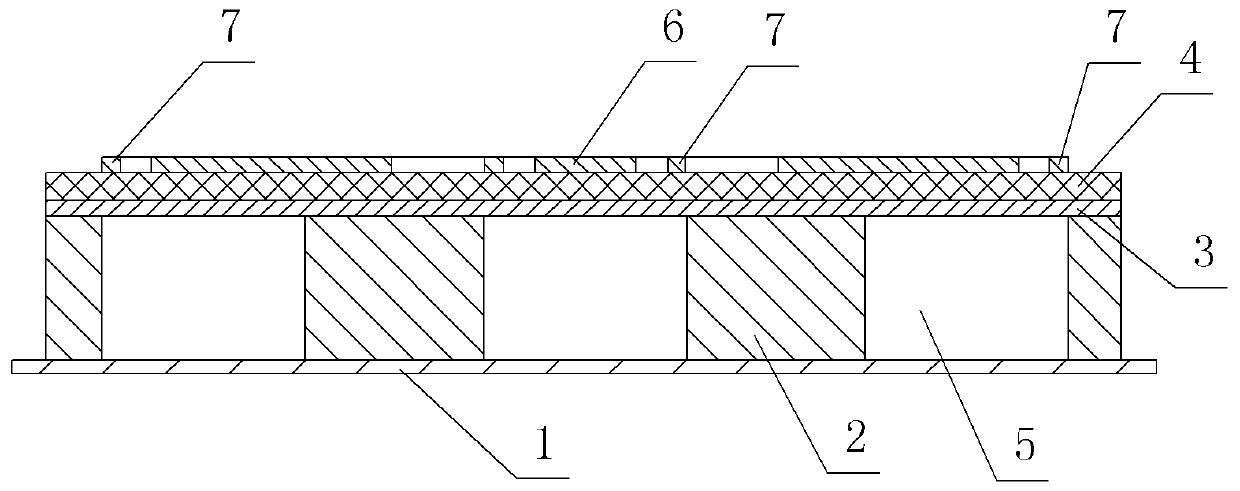
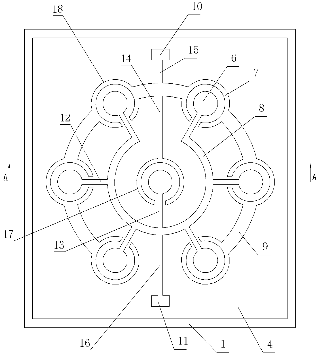
[0037] Embodiment one: if figure 1 ﹑ figure 2 As shown, the piezoelectric ultrasonic transducer includes a top electrode layer, a piezoelectric layer 4, a bottom electrode layer 3, a base layer 2 and a fixed plate 1, the fixed plate 1 is arranged horizontally, and the base layer 2 is arranged on the upper surface of the fixed plate 1 , the bottom electrode layer 3 is arranged on the upper surface of the base layer 2, the piezoelectric layer 4 is arranged on the upper surface of the bottom electrode layer 3, the top electrode layer is arranged on the upper surface of the piezoelectric layer 4, and the top electrode layer contains 7 two identical top electrode units, one of which is the central top electrode unit 17, and the remaining six top electrode units are peripheral top electrode units 18, and the six peripheral top electrode units 18 are evenly distributed around the central top electrode unit 17, The spacing between adjacent top electrode units is half of the waveleng...

Embodiment 2

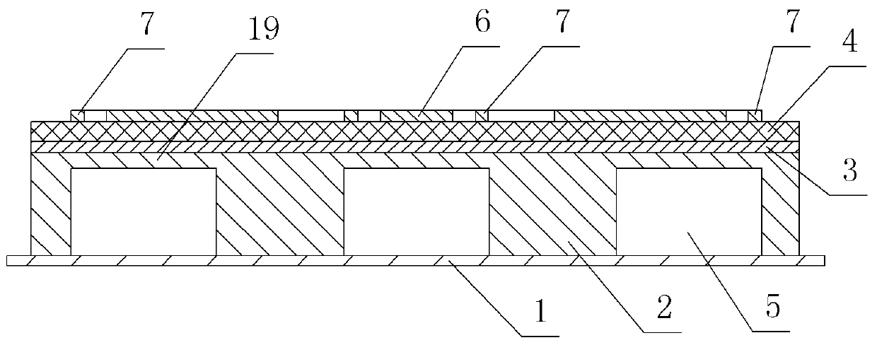
[0058] Embodiment two: if figure 1 ﹑ image 3 As shown, the numbers in the figure are the same as those in Embodiment 1, the representative meanings are the same, and its working process is also basically the same, and the similarities will not be repeated. The difference is: the height of the cavity 5 is less than the height of the base layer 2, and the remaining A part of the base layer 2 above the cavity 5, that is, the cavity 5 stops when the bottom electrode layer 3 is not etched, and a thin film 19 is formed on the cavity 5 as a support to improve the yield and improve the piezoelectricity. The tolerance of the ultrasonic transducer enhances the survivability of the piezoelectric ultrasonic transducer under external damage.


PUM


Abstract

The invention relates to a piezoelectric ultrasonic transducer and a working method thereof. The piezoelectric ultrasonic transducer comprises a top electrode layer, a piezoelectric layer, a bottom electrode layer, a base layer and a fixing plate which are arranged in sequence from top to bottom, and the top electrode layer internally includes a central top electrode unit and N-1 peripheral top electrode units, and the peripheral top electrode units are evenly distributed around the central top electrode unit; each top electrode unit internally includes an inner electrode sheet and an outer electrode sheet, and the outer electrode sheets surround the inner electrode sheets; the inner electrode sheets of the N top electrode units are connected together, and the outer electrode sheets of theN top electrode units are connected together; N cavities are formed in the base layer, the N cavities are separately located right under the N top electrode units; and the piezoelectric ultrasonic transducer can operate in a differential electrode mode and a single electrode mode to emit and receive ultrasonic waves. The piezoelectric ultrasonic transducer has high ability to emit the ultrasonicwaves, is high in sensitivity when receiving ultrasonic waves, is simple in production, can be integrated into a large-scale array, and is diverse and flexible in working methods.

Description

(1) Technical field: [0001] The invention relates to an ultrasonic transducer and its working method, in particular to a piezoelectric ultrasonic transducer and its working method. (two), background technology: [0002] Ultrasonic detection (sensing) technology, as a kind of acoustic sensing technology, is a technology that uses the good directionality, strong penetrating ability and easy to obtain relatively concentrated characteristics of ultrasonic waves to detect physical characteristics such as distance and flow velocity. . Piezoelectric ultrasonic transducer, as the core component of high-end ultrasonic testing equipment, is an energy conversion device that uses piezoelectric effect and inverse piezoelectric effect to perform acoustic-electric and electrical-acoustic conversion. When some parameters of the ultrasonic sound wave emitted by the transducer change due to external physical quantities (such as measurement distance, liquid flow rate, object thickness, etc.),...

Claims


Application Information

Patent Timeline
Patent Type & Authority Applications(China)
IPC IPC(8): B06B1/06
Inventor 牟笑静易拥洁周鸿李东晓
Owner CHONGQING UNIV
Learn More