Driving control circuit and household appliance

A technology for driving control circuits and actions, applied in the field of circuits, can solve problems such as heating up of components, burning out, increasing power consumption of drive control circuits, etc., and achieve the effects of prolonging service life, long working time, and reducing leakage

Pending Publication Date: 2019-05-10
GD MIDEA AIR-CONDITIONING EQUIP CO LTD
View PDF0 Cites 5 Cited by
  • Summary
  • Abstract
  • Description
  • Claims
  • Application Information

AI Technical Summary

Problems solved by technology

[0005] (1) Since it is necessary to continuously power on to control the power supply state of the drive control circuit, it will increase the power consumption of the drive control circuit
[0006] (2) Since the load on the relay is usually an AC signal with a frequency of 50Hz and an effective value of 220V, there is a risk of leakage if the relay is continuously energized
[0007] (3) If the relay is frequently powered on and off, interference pulses such as surge signals and ripple signals will appear in the drive control circuit, which will cause some components in the drive control circuit to heat up sharply, and even be burned, which will not only affect the reliability of local devices, but also increase the thermal crosstalk in the drive control circuit

Method used


Image

  • Driving control circuit and household appliance
  • Driving control circuit and household appliance
  • Driving control circuit and household appliance

Examples


Embodiment 2

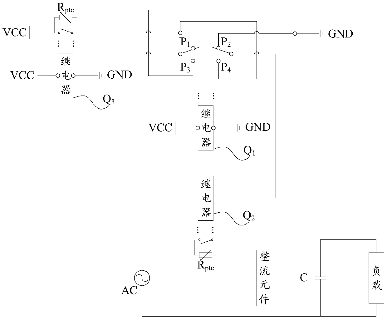
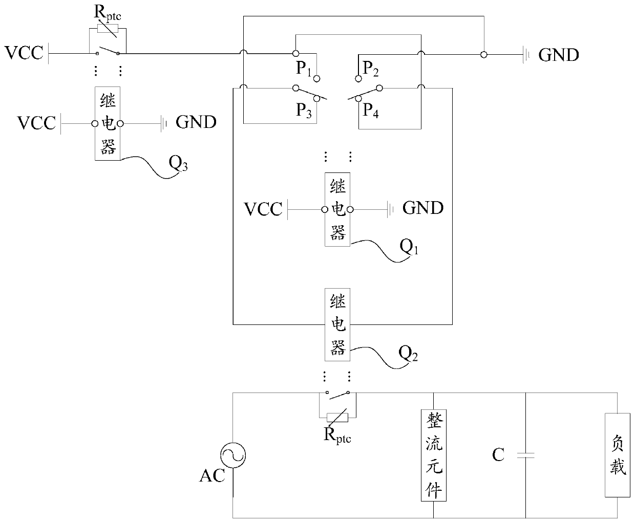
[0073] In view of the problems existing in the traditional relay control scheme, that is, continuous power supply is required during work, this embodiment introduces a self-holding relay control scheme. The self-holding relay is a mechanical relay. In short, it can be self-holding through the mechanical structure after power-on , no need to turn on the power again. For occasions that are in the working state for a long time, the energy consumption is greatly reduced. The longer the working time, the lower the average energy consumption.

[0074] Such as figure 2 and image 3 As shown, the first relay Q is set in the drive control circuit in this embodiment 1 For double-pole double-throw relay, Q 2 As a self-holding relay in the main circuit to control the on-off of the AC signal, to make the self-holding relay Q 2 work, the self-holding relay Q 2 There must be high and low levels on both sides, so the control circuit is also very simple, that is, positive and negative cir...


PUM


Abstract

The invention provides a drive control circuit and a household electrical appliance, the drive control circuit comprises a self-holding relay, a moving contact of the self-holding relay is connected to a power grid system, and when the self-holding relay is in a power-on state, the power grid system can be controlled to supply power to a load; a First relay, wherein the first relay is provided with four contacts, a first contact and a second contact in the four contacts are normally closed contacts, a third contact and a fourth contact in the four contacts are normally open contacts, the firstcontact and the fourth contact are connected to a power supply, the second contact and the third contact are connected to a ground wire, a moving contact of the first relay is connected to a controlend of the self-holding relay, the first relay is configured to output a pulse signal to the self-holding relay, and the pulse signal is a high-level pulse signal or a low-level pulse signal. Throughthe technical scheme of the invention, the power consumption of the driving control circuit is reduced, and meanwhile, the damage risk caused by electric leakage and device temperature rise is reduced, so that the service life is prolonged.

Description

technical field [0001] The present invention relates to the technical field of circuits, in particular, to a drive control circuit and a household electrical appliance. Background technique [0002] As a control component, the relay is widely used in the drive control circuit, and plays the role of automatic adjustment, safety protection, conversion circuit, etc. [0003] For example, in the drive control circuit of the outdoor unit of the inverter air-conditioning system, in order to avoid the excessive input AC current impacting the capacitance when the power is turned on, the traditional relay is often used to limit the charging current, that is, the drive is changed by controlling the power on or off of the relay. Controls the power status of the circuit. [0004] related technologies, such as figure 1 As shown, the traditional relay is in the closed state when the control circuit is working, and the traditional relay and a positive temperature coefficient temperature-...

Claims


Application Information

Patent Timeline
Patent Type & Authority Applications(China)
IPC IPC(8): H03K17/51
Inventor 邱禹文先仕曾贤杰黄招彬
Owner GD MIDEA AIR-CONDITIONING EQUIP CO LTD
Why Eureka
Try Eureka