
Relay zero crossing point trigger circuit, method and device

A relay circuit and trigger circuit technology, applied in circuits, electronic switches, electrical components, etc., can solve problems such as inability to make good contact, increase in contact resistance, and shorten the service life of devices

Pending Publication Date: 2019-05-10
TCL TECH ELECTRONICS (HUIZHOU) CO LTD
View PDF8 Cites 3 Cited by
  • Summary
  • Abstract
  • Description
  • Claims
  • Application Information

AI Technical Summary

Problems solved by technology

However, if there is a high voltage difference between the two ends of the contact at the moment of contact opening and closing, or a large current flows through the contact, sparks and arcs will be generated. The long-term existence of sparks and arcs will gradually damage the compound layer. At the same time, high-temperature arcs may cause plastic machinery. Part of it is deformed, resulting in an increase in contact resistance, or even poor contact, which will reduce the service life of the device in the slightest, and cause electrical hazards in severe cases

Method used


Image

  • Relay zero crossing point trigger circuit, method and device
  • Relay zero crossing point trigger circuit, method and device
  • Relay zero crossing point trigger circuit, method and device

Examples


Embodiment Construction

[0037] The following will clearly and completely describe the technical solutions in the embodiments of the present invention with reference to the accompanying drawings in the embodiments of the present invention. Obviously, the described embodiments are only part of the embodiments of the present invention, not all of them. Based on the embodiments of the present invention, all other embodiments obtained by persons of ordinary skill in the art without creative efforts fall within the protection scope of the present invention.

[0038]It should be noted that all directional indications (such as up, down, left, right, front, back...) in the embodiments of the present invention are only used to explain the relationship between the components in a certain posture (as shown in the accompanying drawings). Relative positional relationship, movement conditions, etc., if the specific posture changes, the directional indication will also change accordingly.

[0039] In addition, the d...


PUM


Abstract

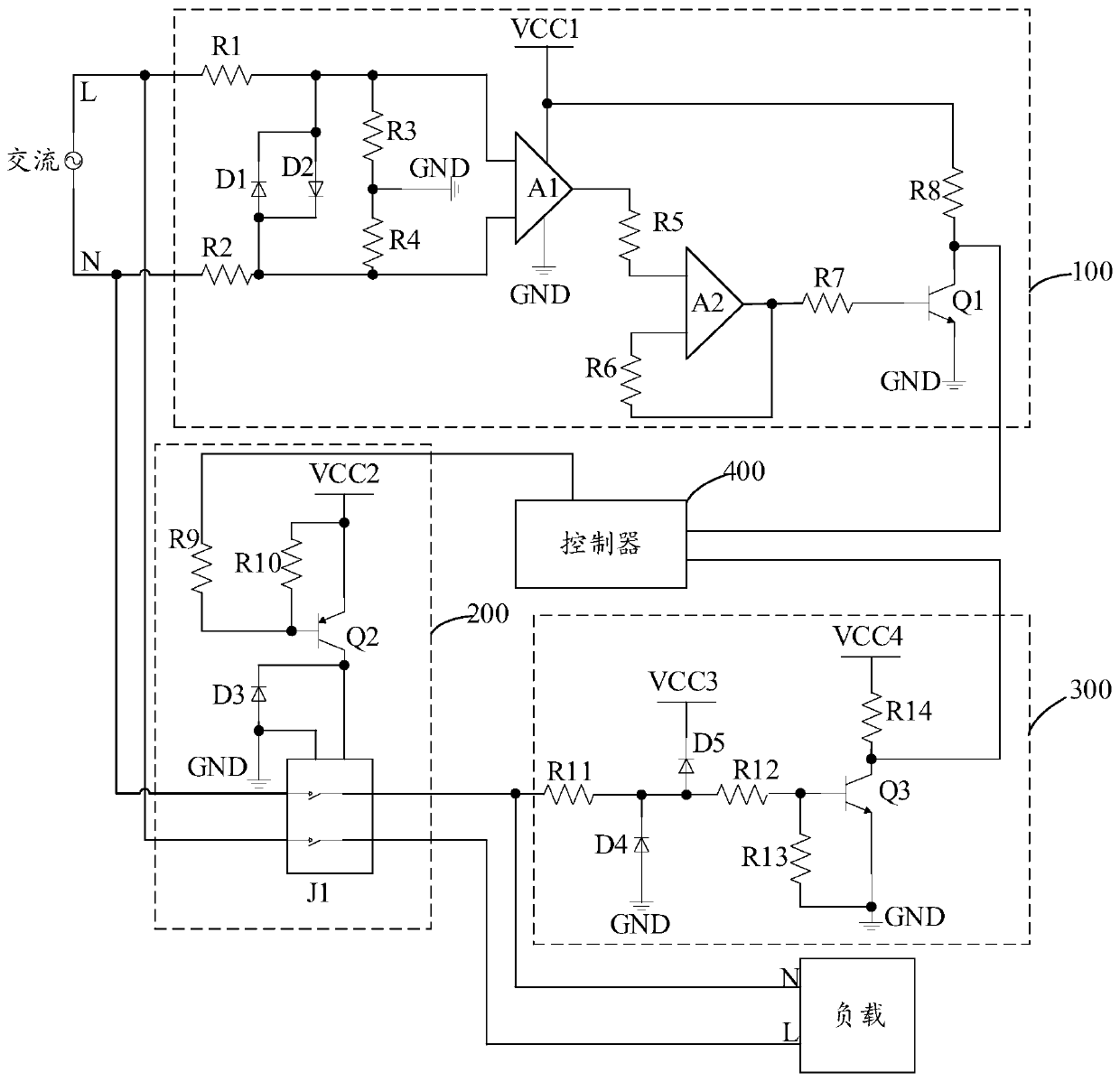
The invention discloses a relay zero-crossing trigger circuit, method and device. The relay zero-crossing trigger circuit comprises a zero-crossing detection circuit, a relay circuit, a level detection circuit and a controller. the relay circuit performs corresponding actions according to action signals sent to the relay circuit by the controller; The level detection circuit collects a level change signal of alternating current and feeds the level change signal back to the controller; The controller calculates a time difference between a time point at which the action signal is sent out and atime point at which the level change signal is received, calculates the delay time based on the time difference and the historical delay time; and the time point of sending the action signal to the relay circuit next time is determined based on the time point of receiving the zero crossing point signal fed back by the zero crossing detection circuit and the current delay time, so that the relay istriggered at the voltage zero crossing point, the service life of the relay is prolonged, and the power utilization safety is improved.

Description

technical field [0001] The invention relates to the technical field of relays, in particular to a relay zero-crossing trigger circuit, method and device. Background technique [0002] The use of relays can be seen everywhere in production and life. With its characteristics of controlling large current and high voltage with small current and low voltage, it is widely used in various switching circuits, automatic adjustment circuits, safety protection circuits, and conversion circuits. Although there are many types and different application scenarios, the basic function is to control the opening and closing of contacts. However, if there is a high voltage difference between the two ends of the contact at the moment of contact opening and closing, or a large current flows through the contact, sparks and arcs will be generated. The long-term existence of sparks and arcs will gradually damage the compound layer. At the same time, high-temperature arcs may cause plastic machinery....

Claims


Application Information

Patent Timeline
IPC IPC(8): H03K17/28H03K17/51H03K17/74
Inventor 徐鑫孙国伟
Owner TCL TECH ELECTRONICS (HUIZHOU) CO LTD
Learn More