
A design method of a cylindrical radial uniform magnetic field coil

A technology of uniform magnetic field and design method, applied in computing, special data processing applications, instruments, etc., can solve the problems of affecting the relaxation rate of atomic sources, limiting the degree of miniaturization of SERF atomic magnetometers, and redundant volumes, etc. Reliable precision, easy processing and practical structure

Inactive Publication Date: 2019-05-10
BEIHANG UNIV
View PDF9 Cites 4 Cited by
  • Summary
  • Abstract
  • Description
  • Claims
  • Application Information

AI Technical Summary

Problems solved by technology

Among them, the three-dimensional magnetic field coil is used to generate a uniform spatial magnetic field. It is not only an actuator for actively compensating the magnetic field, but also a device for generating magnetic field excitation signals. Its structure limits the miniaturization of the SERF atomic magnetometer. At the same time, its magnetic field is uniform degree affects the relaxation rate of the atomic source
Usually, in SERF atomic magnetometers, saddle-shaped coils are mostly used to generate radially uniform magnetic fields. However, when the saddle-shaped coils generate uniform magnetic field performance is optimal, the ratio of its length to diameter reaches 1.75, and the redundant volume is too much

Method used


Image

  • A design method of a cylindrical radial uniform magnetic field coil
  • A design method of a cylindrical radial uniform magnetic field coil
  • A design method of a cylindrical radial uniform magnetic field coil

Examples


Embodiment Construction

[0036] Below in conjunction with accompanying drawing, the present invention is described in further detail:

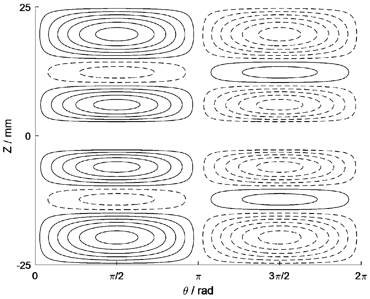
[0037] Such as figure 1 As shown, the design process of a design method of a cylindrical radial uniform magnetic field coil of the present invention is as follows: first, the surface of the coil is divided into equal parts along the axial direction according to the azimuth angle θ=π of the cylindrical coordinate system, and the surface current on one side is determined Density expression, the current density distribution on the other side is exactly the same, but the current direction is opposite. Secondly, deduce the magnetic field expression of the target field point, select the curvature of the current density as the penalty function of the confinement coil, set the constraint factor of the penalty function, use the regularization method to solve the value of the undetermined coefficient in the current density expression, and obtain the cylindrical surface Current...


PUM


Abstract

The invention discloses a design method of a cylindrical radial uniform magnetic field coil, which comprises the following steps of: firstly, equally dividing the surface of the coil along the axial direction according to the azimuth angle of a cylindrical coordinate system, determining the surface current density expression on one side, and determining that the current density distribution on theother side is completely the same as that on the other side but opposite in current direction; secondly, deducing a magnetic field expression of a target field point, selecting the curvature of the current density as a penalty function of a constraint coil, setting a constraint factor of the penalty function, and solving a value of an undetermined coefficient in the current density expression byutilizing a regularization method to obtain a current density distribution condition of the cylindrical surface; and finally, obtaining an actual current routing shape of the cylindrical radial uniform magnetic field coil by using a flow function. The method serves as an inverse method of coil design, the size of the cylindrical coil is limited in advance, the coordinate position of a target fieldpoint is selected, then actual current distribution of the coil is obtained through calculation, the length-diameter ratio of the cylindrical coil is effectively controlled, and a gap can be reservedin the center of the coil to form a light through hole.

Description

technical field [0001] The invention belongs to the technical field of atomic magnetometers, and in particular relates to a design method of a cylindrical radial uniform magnetic field coil. Background technique [0002] With the advancement of science and technology, atomic magnetometer technology has been greatly developed in recent years, from optically pumped magnetometers and nuclear magnetic resonance magnetometers based on the principle of magnetic resonance to superconducting quantum interference magnetometers based on the Josephson effect. The development process of atomic magnetometer based on spin-free exchange effect (SERF) from strong meter (SQUID). The SERF atomic magnetometer uses the atomic spin effect to measure the magnetic field, and its magnetic field limit measurement sensitivity is better than that of the SQUID. It is considered to be a type of magnetometer with the most potential for extremely weak magnetic detection. [0003] The SERF atomic magnetom...

Claims


Application Information

Patent Timeline
Patent Type & Authority Applications(China)
IPC IPC(8): G06F17/50
Inventor 周斌权房建成韩邦成王婧尹彦尹凯峰唐钧剑
Owner BEIHANG UNIV
Learn More