
Retracting and releasing mechanism of binding device

A technology of retractable mechanism and binding device, which is applied in the direction of binding machine parts, etc., can solve problems such as falling off, worm stuck, screw loose, etc., and achieve the effect of fast and smooth axial movement during the switching process

Active Publication Date: 2019-05-10
ANJI AUTOMOTIVE LOGISTICS +1
View PDF5 Cites 3 Cited by
  • Summary
  • Abstract
  • Description
  • Claims
  • Application Information

AI Technical Summary

Problems solved by technology

Such a structure is easy to install, simple in structure and low in cost, but in actual use, there will be some shortcomings: first, when the tightener is switched from the take-up state to the slack state, the worm needs to move axially from the meshing state to the In the non-meshing state, if the positioning pin wants to guide the axial movement of the worm, the positioning pin needs to be embedded in the worm teeth of the worm
However, during the axial movement of the worm of the device from the meshing state to the non-meshing state, the worm will conflict with the positioning pin. At this time, only the rotation of the worm can be relied on. When the worm rotates to a certain angle, the positioning pin can be inserted into the worm Therefore, the design of the positioning pin will form a certain resistance to the axial movement of the worm, and the worm will be stuck, resulting in the unsmooth axial movement of the worm, which will affect the winding and unwinding of the tightener. The smoothness and efficiency of the switching process; second, when the axial movement of the worm conflicts with the positioning pin, it will push the positioning pin to move axially towards the outer end. When the component force of the inclined swinging trend occurs, the positioning pin will rub against the wall of the connecting hole when the positioning pin tilts, making it more difficult for the positioning pin to expand and contract in the axial direction, which further aggravates the situation of the axial movement of the worm screw; third, the positioning pin passes through The screw is used for positioning, and the screw is threadedly connected with the connecting hole. At this time, if the screw is too tight, the axial displacement of the positioning pin will be small, which will aggravate the jamming of the axial movement of the worm; but if the screw is too loose , which will cause the screws to loosen or even fall off
The above reasons lead to low switching efficiency and smoothness of the device during the switching process of receiving and releasing the binding belt.

Method used


Image

  • Retracting and releasing mechanism of binding device
  • Retracting and releasing mechanism of binding device
  • Retracting and releasing mechanism of binding device

Examples


Embodiment 1

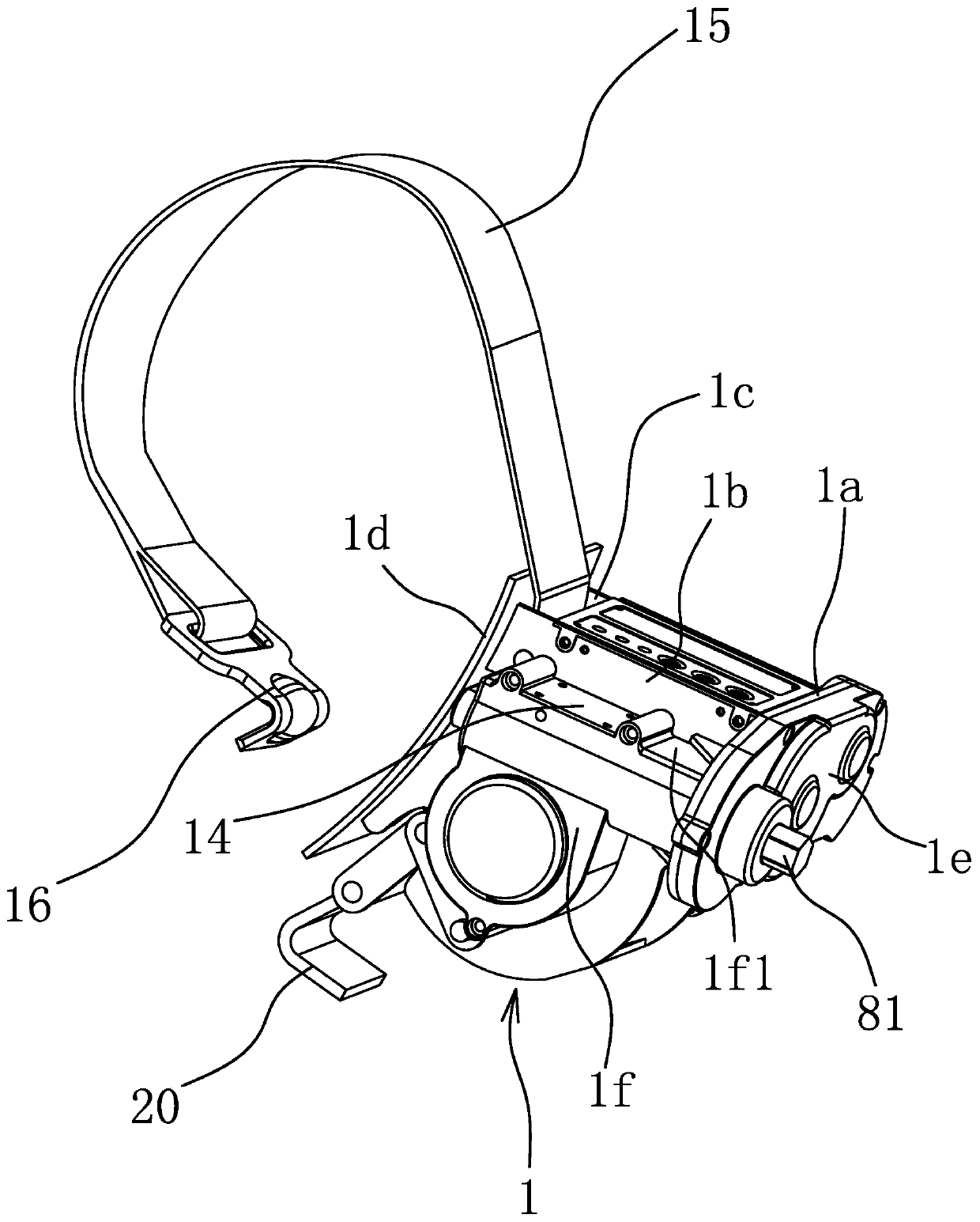
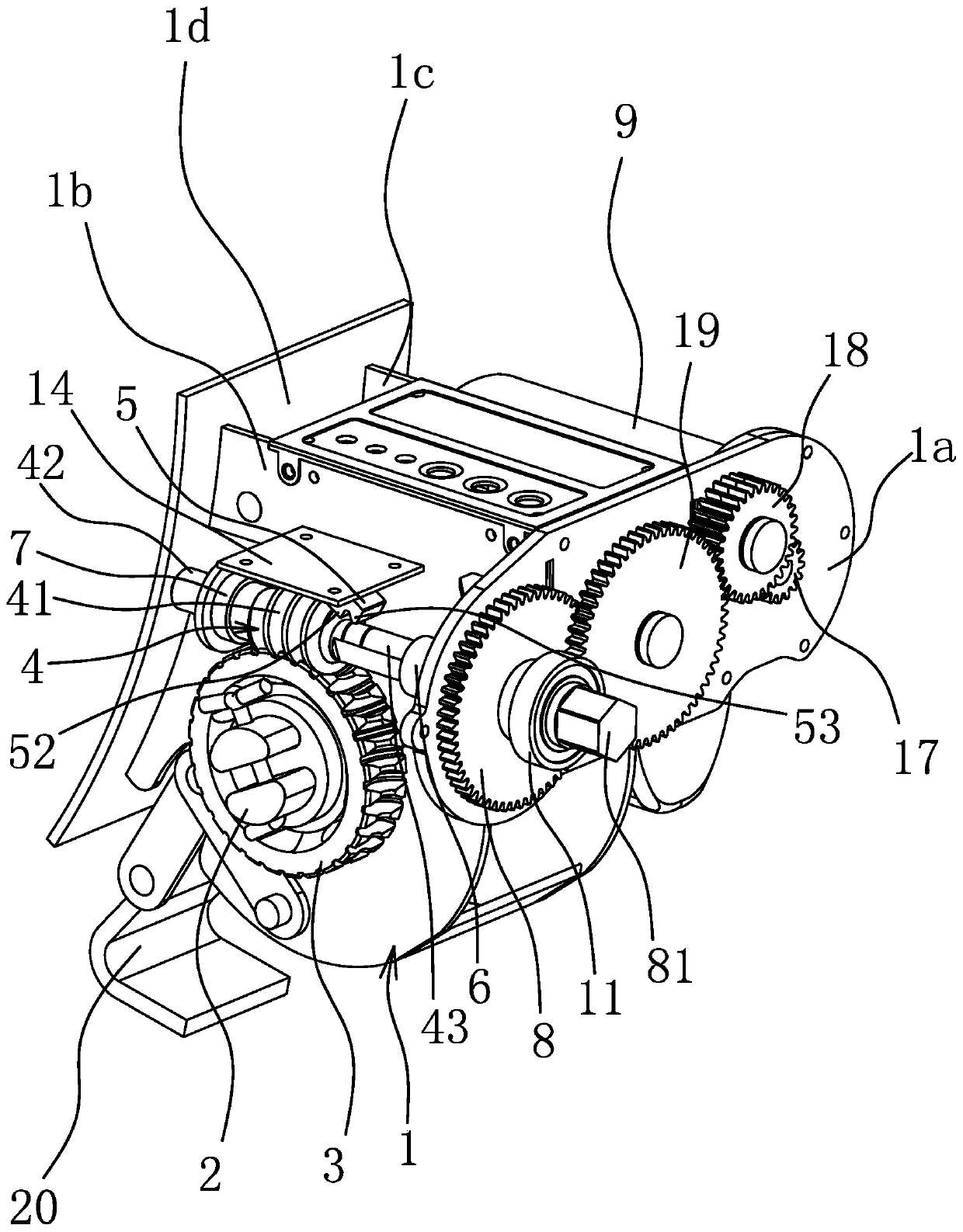
[0045] The binding device in this embodiment is a wheel fixer, which is used to bind and fix the wheels of the vehicle during the transportation of the vehicle, so as to prevent the vehicle from shifting during transportation and ensure the safety of transportation. Of course, the retractable mechanism of the binding device can also be used for other binding equipment, such as a winch or a binding device for binding and fixing goods. Such as figure 1 As shown, the binding device includes a housing 1, a binding member 15 and a reel 2 rotatably arranged on the housing 1, the binding member 15 is a webbing, the webbing is wound on the reel 2, and the protruding end of the webbing is connected with a belt hook 16, A hook 20 is connected to the housing 1 through a chain link. Housing 1 includes abutting plate 1d, mounting plate 1a, side plate 1b, side plate 2 1c, gear cover 1e, worm gear cover 1f, side plate 1b and side plate 2 1c are oppositely arranged, and mounting plate 1a is ...

Embodiment 2

[0060] The structure and principle of this embodiment are basically the same as that of Embodiment 1, except that the included angle between the pushing plane 521 and the axis of the worm 4 is 25 degrees when the claw 5 swings toward the limit position in the direction close to the worm 4 .

Embodiment 3

[0062] The structure and principle of this embodiment are basically the same as that of Embodiment 1, except that the included angle between the pushing plane 521 and the axis of the worm 4 is 50 degrees when the claw 5 swings toward the limit position in the direction close to the worm 4 .


PUM


Abstract

The invention provides a retracting and releasing mechanism of a binding device and belongs to the technical field of logistics binding equipment. The retracting and releasing mechanism of the bindingdevice solves the problem that a binding device in the prior art is not high in switching efficiency and smoothness degree in the switching process for retracting and releasing a binding belt. The retracting and releasing mechanism of the binding device comprises a worm gear connected to a binding device reel and synchronously rotating with the reel; a shell of the binding device is provided witha worm; a clamping claw located on the side portion of the worm is hinged to the shell, and is provided with lifting clamping teeth capable of being embedded into a tooth groove of spiral teeth so asto guide the worm to move in the axial direction when the worm rotates; when the worm moves in the axial direction from the state that the worm is engaged with the worm gear to the state that the worm disengages from the worm gear, the lifting clamping teeth can be ejected and pushed by the spiral teeth so that the clamping claw can swing in the direction away from the worm; and the amplitude ofswinging of the clamping claw in the direction away from the worm can make the lifting clamping teeth higher than a tooth crest of the spiral teeth. The retracting and releasing mechanism of the binding device has the beneficial effect that the swinging process for retracting and releasing the binding piece is fast and smooth.

Description

technical field [0001] The invention belongs to the technical field of logistics binding equipment, and relates to a retractable mechanism of a binding device. Background technique [0002] During the transportation of the goods, the goods need to be bound and fixed to prevent the goods from shifting and shaking during transportation and ensure the safety of transportation. A binding device is a device that binds and fixes goods through binding parts such as webbing, binding ropes, and steel wire ropes. The binding device generally includes a reel for winding the binding, and the binding is tightened or loosened by rotating the reel. [0003] Some binders use worm gears and worm mechanisms to drive the reel to rotate, such as a belt retracting device for a tightener disclosed in Chinese patent documents (application number: CN200810187640.2, date of authorization announcement: 2012, November, 28). The tape unwinding device includes a housing fixedly connected to the side o...

Claims


Application Information

Patent Timeline
Patent Type & Authority Applications(China)
IPC IPC(8): B65B13/18B65H75/38B65H75/44
Inventor 阮卜琴肖招银牛胜良
Owner ANJI AUTOMOTIVE LOGISTICS
Learn More