
Automatic edge covering equipment

A technology of hemming and equipment, applied in the field of automatic hemming equipment, can solve the problems of offset or falling off of hemming, difficulty in ensuring the same hammering force, poor uniformity of hemming quality, etc., so as to achieve fast hemming and avoid hemming. Uneven quality, the effect of ensuring the quality of the hemming

Pending Publication Date: 2019-05-10
JINAN WEIER LASER EQUIP
View PDF10 Cites 4 Cited by
  • Summary
  • Abstract
  • Description
  • Claims
  • Application Information

AI Technical Summary

Problems solved by technology

[0002] For the sake of beauty and reinforcement, the edge of the automotive interior panel needs to be hemmed. At present, most manufacturers still use manual hammering to cover and extrude the alloy strip on the edge of the interior panel during the hemming operation. , not only the workload is heavy and the efficiency is low, but also the hemming is prone to shift or fall off during the manual operation, and it is difficult to ensure the same strength of each hammering, resulting in poor quality uniformity of hemming and affecting the appearance
[0003] Although there are also related reports about fully automatic hemming equipment, the structure of the related equipment is complex, the cost is high, and it is difficult to popularize and apply it on a large scale.
Moreover, automotive interior panels are often irregular in shape. Using fully automatic edge wrapping equipment requires complex procedures to match the edge wrapping path. If there are inner holes on the board, the operation is more troublesome when wrapping the inner holes.
Moreover, the existing hemming tools need a certain radius of gyration when turning corners. When operating into a deep groove with a small curvature radius, it is difficult to turn, and the hemming must be performed by manual hammering, which cannot effectively solve the problem. question

Method used


Image

  • Automatic edge covering equipment
  • Automatic edge covering equipment
  • Automatic edge covering equipment

Examples


Embodiment Construction

[0036] In order to clearly illustrate the technical features of this solution, the present invention will be described in detail below through specific implementation modes and in conjunction with the accompanying drawings.

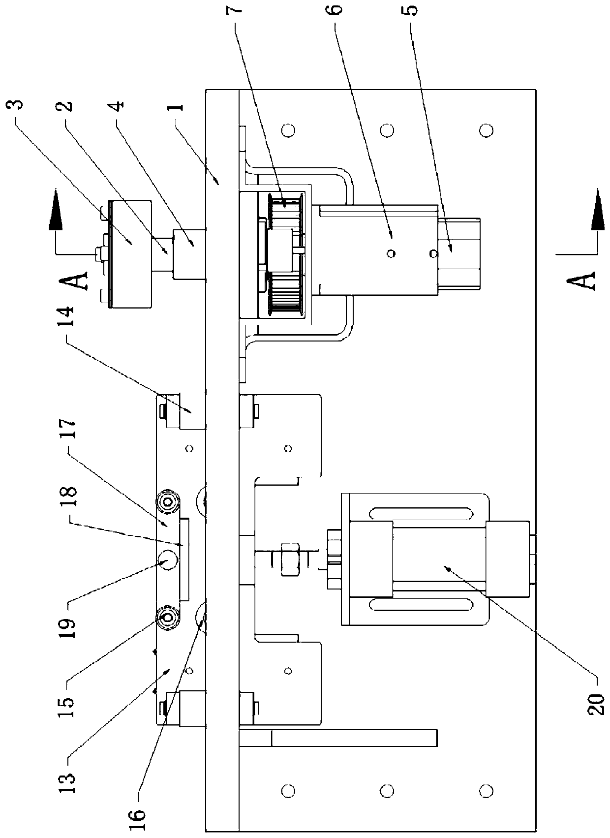
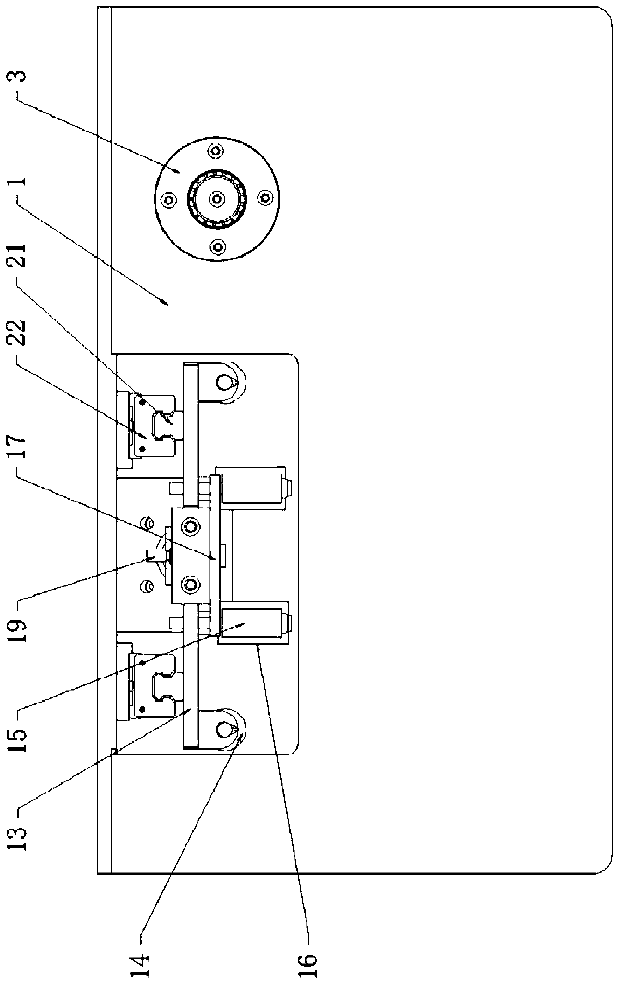
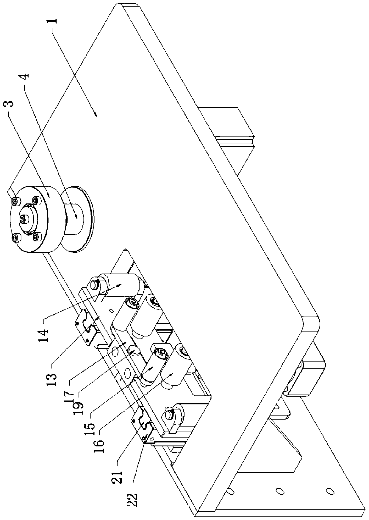
[0037] Such as Figure 1-Figure 6 As shown in , the automatic hemming equipment of this embodiment includes a workbench 1, on which a primary extrusion unit is provided, and the primary extrusion unit includes:

[0038] A guide shaft 2, the guide shaft 2 passes through the worktable 1, and the guide shaft 2 can move axially. In order to realize automatic operation, the guide shaft 2 can be connected with a moving mechanism that controls its axial movement;

[0039] Rotate the pressure roller 3 sleeved on the guide shaft 2, and the pressure roller 3 cooperates with the worktable 1 to squeeze the upper and lower surfaces of the hemming once;

[0040] Rotate the sleeve 4 sleeved on the guide shaft 2 to squeeze the side of the hemming once. The sleeve 4 can...


PUM


Abstract

The invention discloses automatic edge covering equipment which comprises a worktable. A primary extruding unit is arranged on the worktable and comprises a guide shaft, a pressing wheel and a sleeve,wherein the pressing wheel is rotatably arranged on the guide shaft in a sleeving manner and the sleeve is rotatably arranged on the guide shaft in a sleeving manner. According to the automatic edgecovering equipment, the side face of a covered edge leans against the sleeve of the primary extruding unit and a guide roller of the secondary extruding unit, and the upper and lower surfaces of the covered edge are extruded by the pressing wheel, the worktable, a first extruding roller and a second extruding roller, so that the side face and the upper and lower surfaces of the covered edge compress the edge of a decorative plate so as to prevent the covered edge from shifting or falling off; the sleeve is driven by a motor to rotate to drive the covered edge leaning against the sleeve to moveforward so as to extrude an aluminum alloy strip to the edge of the decorative plate continuously by pushing the decorative plate forward by matching with an operator.

Description

technical field [0001] The invention relates to an automatic hemming device. Background technique [0002] For the sake of beauty and reinforcement, the edge of the automotive interior panel needs to be hemmed. At present, most manufacturers still use manual hammering to cover and extrude the alloy strip on the edge of the interior panel during the hemming operation. , not only the workload is heavy and the efficiency is low, but also the hemming is prone to shift or fall off during manual operation, and it is difficult to ensure the same strength of each hammering, resulting in poor quality uniformity of hemming and affecting the appearance. [0003] Although there are also related reports about fully automatic hemming equipment at present, the structure of the related equipment is complicated and the cost is high, so it is difficult to popularize and apply it in a large scale. Moreover, automotive interior panels are often irregular in shape. Using fully automatic hemming...

Claims


Application Information

Patent Timeline
Patent Type & Authority Applications(China)
IPC IPC(8): B29C65/64B29L31/30
CPCY02E60/10
Inventor 李祥福寇扬纪晓静
Owner JINAN WEIER LASER EQUIP
Learn More