A two-state variable stiffness compliant joint and its operating method

A variable stiffness, two-state technology, applied in the field of robotics, can solve problems such as difficulty in ensuring joint stiffness, and achieve the effects of good human-computer interaction safety, good impact resistance, and good torque transmission characteristics.

Active Publication Date: 2021-09-07
XI AN JIAOTONG UNIV
View PDF16 Cites 0 Cited by
  • Summary
  • Abstract
  • Description
  • Claims
  • Application Information

AI Technical Summary

Problems solved by technology

More importantly, the currently disclosed stiffness-adjustable joints are all continuously adjustable in stiffness, and it is bound to be difficult to ensure that the joint stiffness can be adjusted to the required value in a timely and accurate manner. Extremely fast transitions of stiffness values

Method used


Image

  • A two-state variable stiffness compliant joint and its operating method
  • A two-state variable stiffness compliant joint and its operating method
  • A two-state variable stiffness compliant joint and its operating method

Examples


Embodiment 1

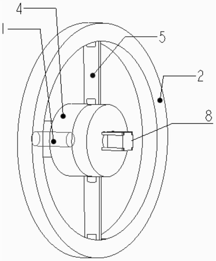
[0036] like figure 1 and figure 2 As shown, a two-state variable stiffness compliant joint at least includes an input shaft 1, an output outer ring 2 and a stiffness adjustment mechanism: the input shaft 1 is set at the center of rotation of the output outer ring 2, and is the same as the input shaft 1 The input disk 4 of the shaft center is fixedly connected, and the output outer ring 2 is connected with the input disk 4 through a rotating pair; the input disk 4 and the output outer ring 2 are connected through a supporting elastic reed 5; the stiffness adjustment mechanism includes a stiffness adjustment motor 8, a second Two bevel gears 9, the first bevel gear 3; the motor 8 is fixedly connected with a second bevel gear 9; the second bevel gear 9 meshes with two first bevel gears 3 that are fixedly connected with the elastic reed 5 to form a gear transmission connection .

[0037] There are multiple (3-6) elastic reeds 5, the plurality of elastic reeds 5 are evenly distr...

Embodiment 2

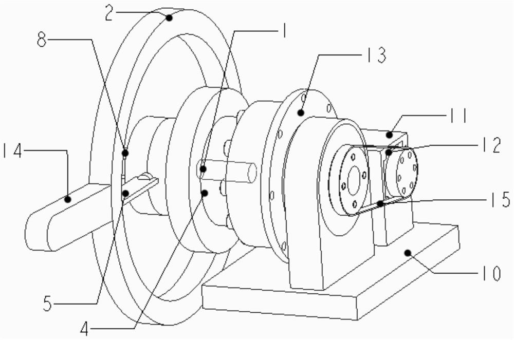
[0041] like image 3 As shown, the main frame of this example is a frame 10, on which a motor bracket 11 is installed; the main motor 12 is fixed on the motor bracket 11 through a flange, and is connected to the input shaft 1 through a conveyor belt 15, and the harmonic reducer 13 to the transmission mechanism, the transmission shaft is connected with the input disk 4, connected with the power output outer ring 2 through the elastic reed 5, and the elastic reed 5 is connected with the input disk 4 and the output outer ring 2 by the bearing 6.

[0042] The adjusting motor 8 is fixed on the input disc 4 through a flange, and is connected with the second bevel gear 9 through the adjusting motor coupling, and the first bevel gear 3 is fixedly connected with the elastic reed 5 .

[0043] When this example is running, the input disk 4 is rigidly driven by the main motor 12, and the elastic reed 5 is deformed to drive the output outer ring 2 to rotate. When the stiffness adjustment m...


PUM


Abstract

The invention discloses a two-state variable stiffness compliant joint and an operation method thereof. The joint is composed of an input shaft, an output outer ring and a stiffness adjustment mechanism. The input shaft is placed at the center of rotation of the output outer ring and is firmly connected to the input disc; two elastic reeds are installed between the input disc and the output outer ring, one end of each elastic reed is connected to the output outer ring through a bearing, and the other end is connected to the output outer ring. The small bevel gear shaft is fixedly connected, and the small bevel gear shaft is connected to the input plate through bearings; the stiffness adjustment mechanism is fixedly connected to the large bevel gear through the stiffness adjustment motor; the large bevel gear is connected to two small bevel gears that are fixedly connected to the elastic reed engage. The invention has good impact resistance and flexible dynamic characteristics, belongs to active variable stiffness compliant joints, and can be used for joints and drivers of various robots such as bionics, service and rehabilitation.

Description

technical field [0001] The invention belongs to the technical field of robots, and in particular relates to a two-state variable stiffness compliant joint and an operation method. Background technique [0002] With the development of robot technology, the collaborative work of multiple robots and the interaction between robots and humans are becoming more and more common in terms of flexibility. Robots have been applied from traditional fields to other non-industrial fields, especially the rise of bionic robots, service robots and rehabilitation robots, forcing the robot joints to have a certain degree of compliance to ensure the improvement of energy utilization and improve the safety of human-computer interaction Assure. [0003] From the perspective of the overall structure of the robot, the robot joints are the key components for the robot to achieve various target movements. Rigid joints and elastic joints are mainly used in the existing robot technology. There are r...

Claims


Application Information

Patent Timeline
Patent Type & Authority Patents(China)
IPC IPC(8): B25J17/02
Inventor 陈贵敏辛洪旭马付雷李博
Owner XI AN JIAOTONG UNIV
Why Eureka
Try Eureka