Blocking and sopping mechanism and drawing-pulling type water outlet device

A snap ring and snap sleeve technology, applied in the field of kitchen and bathroom, can solve the problems of complicated assembly, long life of the overall solution, inconvenient operation, etc., and achieve the effect of easy identification, good experience, and easy listing.

Pending Publication Date: 2019-05-07
JOMOO KITCHEN & BATHROOM
View PDF12 Cites 6 Cited by
  • Summary
  • Abstract
  • Description
  • Claims
  • Application Information

AI Technical Summary

Problems solved by technology

[0003] However, there are many problems in the existing drawable water outlet terminal, such as complex structure, not compact, inconvenient operation, etc.
For example, in a drawable water outlet terminal, the drawer tube is reset by a heavy hammer or other heavy objects, so that when the user uses the pull function, the user needs to keep pulling the water outlet terminal, otherwise the water outlet terminal will be damaged. The hammer is reset due to falling under the action of gravity, which makes the user prone to fatigue during use, and the experience is not good and very inconvenient
[0004] The stop mechanism of pull-out faucets has appeared on the market. Its structure is complex, there are many cumbersome assembly procedures, the number of parts is large, the parts require high precision, the life of the overall solution is big, and the cost of each solution is too high; None of the positions can be adjusted
And if it is necessary to increase the number of stop stages, the more complex the trajectory of the steel ball is, it is basically difficult to achieve multi-stage stop
Due to the above reasons, the current patents including domestic and foreign hose clamping have never been actually applied and listed on the market.

Method used


Image

  • Blocking and sopping mechanism and drawing-pulling type water outlet device
  • Blocking and sopping mechanism and drawing-pulling type water outlet device
  • Blocking and sopping mechanism and drawing-pulling type water outlet device

Examples


Embodiment 1

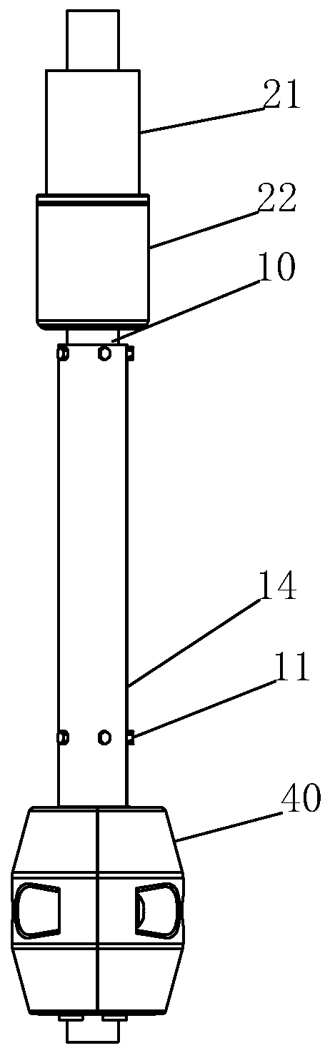
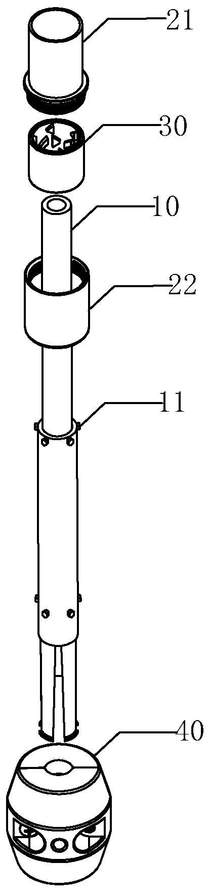
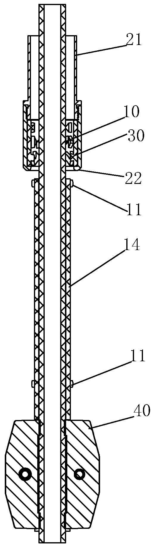
[0047] refer to Figure 1 to Figure 3 , a locking mechanism, including a tube body group, a fixed sleeve 20 and a snap ring 30, the tube body group is provided with a tube body 10 and a return member 40, etc., the tube body 10 can be a flexible pipe or a hard tube, and the fixed sleeve 20 Adopt one-piece structure. At least one bump group is provided on the tube body 10, and each bump group is provided with a plurality of bumps 11, and the plurality of bumps 11 are distributed circumferentially. The protruding point 11 can be a protruding block or a partially embedded movable steel ball. If it is a protruding block, it can be in the shape of a rhombus, an ellipse, a circle, etc., such as a rhombus. The upper slope 12, the bottom is provided with the lower slope 13 extending upwards along both sides respectively. The number of the bump groups can be one group, two groups, three groups or even more, and the number of bump groups represents the number of stops that can be achie...

Embodiment 2

[0073] refer to Figure 9 to Figure 11 , a locking mechanism, the pipe body 10 only needs to be locked when the longest drawing length is required, and only a group of uniformly distributed bumps 11 are required on the pipe body 10, and at the same time, the fourth convex Block 37 is taken and removed, and the positioning of the longest drawing length of the limit pipe body 10 can be realized. details as follows:

[0074] It includes a tube body set, a fixing sleeve 20 and a snap ring 30. The tube body set is provided with a tube body 10 and a return piece 40, etc., and the tube body 10 can be a hose or a hard tube. In this embodiment, only one bump group is provided on the tube body 10 (that is, the number of locking stages that can be realized is 1), and the bump group is provided with a plurality of bumps 11, and the plurality of bumps 11 are circumferentially distributed. The protruding point 11 can be a protruding block or a partially embedded movable steel ball. If it ...


PUM


Abstract

The invention discloses a blocking and stopping mechanism, and a drawing-pulling type water outlet device. The blocking and stopping mechanism comprises a tube body group and a fixed sleeve, and further comprises a blocking ring and a return part, wherein the fixed sleeve sleeves the tube body group; at least one convex point group is arranged on the tube body group; each convex point group is equipped with a plurality of convex points which are distributed in the peripheral direction; the blocking ring is arranged between the tube body group and the fixed sleeve in a sleeving mode, and a plurality of bumps are arranged in the blocking ring sleeve; the bumps further define a plurality of channels for allowing the convex points to pass through, and a plurality of locking slots for blockingand stopping the convex points; and the return part is connected to the tube body group. The blocking and stopping mechanism can realize functions such as drawing-pulling, retracting and blocking-stopping of the tube body group, is convenient in operation, has fewer parts, is easily realized, and is low in cost.

Description

technical field [0001] The invention relates to the field of kitchen and bathroom, in particular to a locking mechanism and a pull-out water outlet device. Background technique [0002] At present, the pullable water outlet terminals in the prior art, such as pull-out showers, pull-out faucets, etc., are connected with a pull-out pipe. When the pull-out function does not need to be realized, the water outlet terminal is generally positioned on the installation body. The water can be discharged in the set direction; when the pulling function is needed, the user only needs to pick up the water outlet terminal and pull the water outlet terminal to move the water outlet terminal to a suitable position for water outlet, which is convenient for users to wash their hair and face, etc. . [0003] However, there are many problems in the existing drawable water outlet terminal, such as complex structure, not compact, inconvenient operation and so on. For example, in a drawable water...

Claims


Application Information

Patent Timeline
Patent Type & Authority Applications(China)
IPC IPC(8): F16K27/00E03C1/04
Inventor 林孝发林孝山张传义游新友温晨广
Owner JOMOO KITCHEN & BATHROOM
Why Eureka
Try Eureka