Linear compressor

A linear compressor and linear motor technology, applied in the field of compressors, can solve problems such as the risk of large compressor pistons and cylinders being stuck, the overall structure and shape of the compressor are short, and the compression efficiency is affected. , The effect of reducing the external size and increasing the suction volume

Active Publication Date: 2019-05-07
TECHNICAL INST OF PHYSICS & CHEMISTRY - CHINESE ACAD OF SCI
View PDF4 Cites 2 Cited by
  • Summary
  • Abstract
  • Description
  • Claims
  • Application Information

AI Technical Summary

Problems solved by technology

This structure makes the heat generated in the process of compressing gas by the linear compressor and the heat generated by the motor itself affect each other, affecting the compression efficiency. At the same time, the overall structure of the compressor tends to be short and high.
[0004] In order to overcome the above disadvantages, the linear compressor in the prior art will arrange the compression chamber composed of the cylinder, the piston and other components on the outside of the cylindrical linear motor, and use the low-temperature and low-pressure gas to compress the inside and outside of the linear motor. The outer side of the cavity is used to dissipate heat, which improves the efficiency and reliability of the linear compressor. However, due to the very high requirements for assembly coaxial precision after the cylinder and piston are placed outside, there is a greater risk of the compressor piston and cylinder being stuck.

Method used


Image

  • Linear compressor
  • Linear compressor
  • Linear compressor

Examples


Embodiment Construction

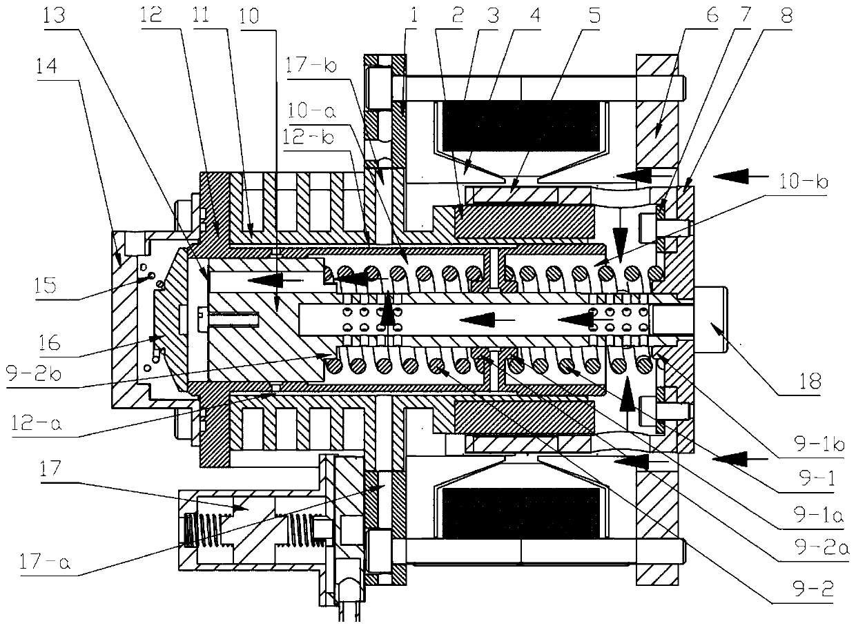
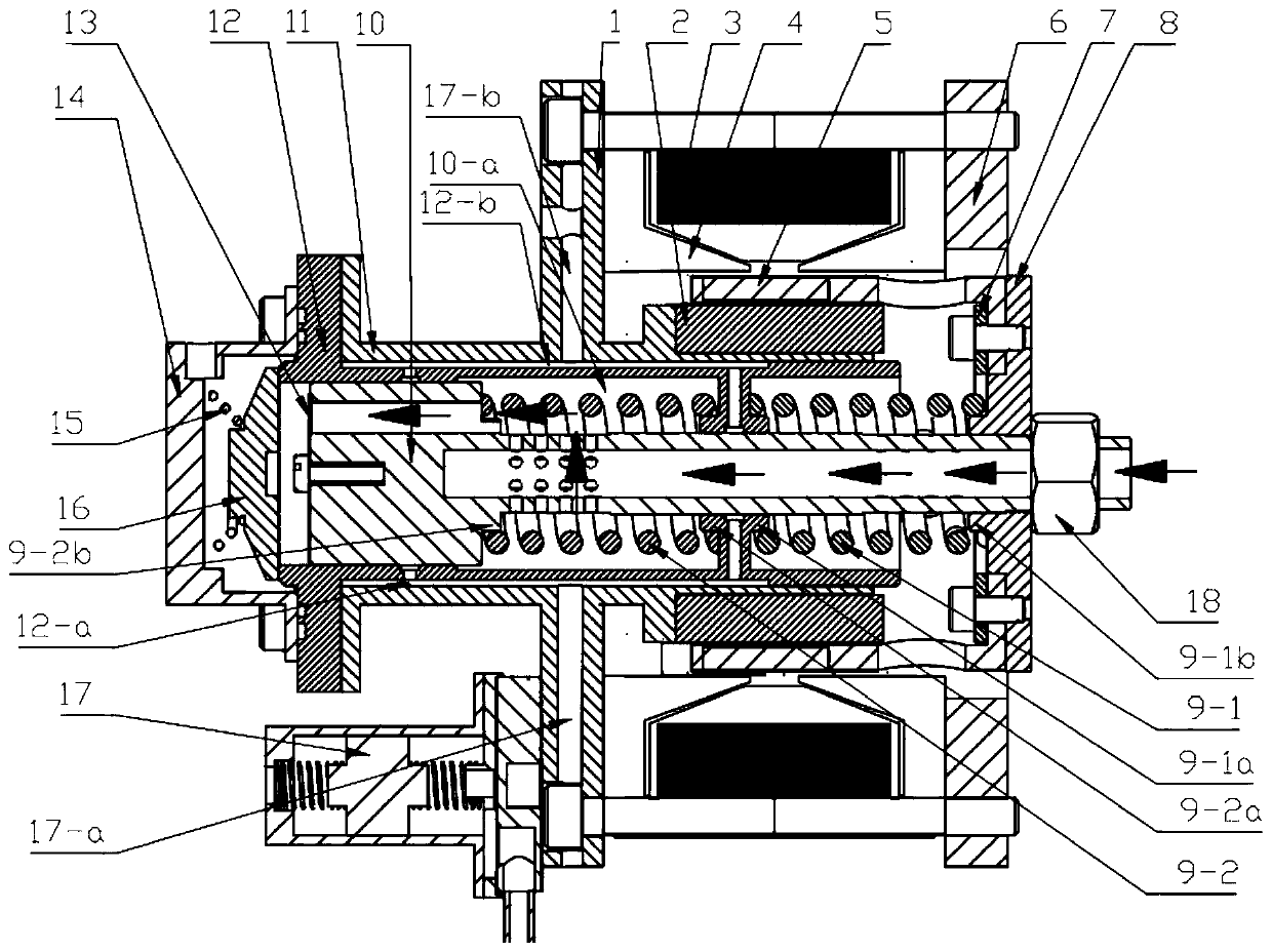
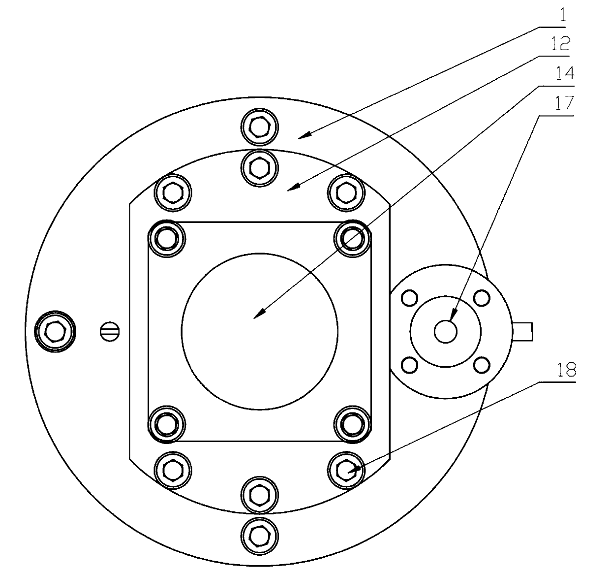
[0027] In order to make the object, technical solution and advantages of the present invention clearer, the present invention will be further described in detail below in combination with specific embodiments and with reference to the accompanying drawings. It should be understood that these descriptions are exemplary only, and are not intended to limit the scope of the present invention. Also, in the following description, descriptions of well-known structures and techniques are omitted to avoid unnecessarily obscuring the concept of the present invention.

[0028] A schematic diagram of a layer structure according to an embodiment of the invention is shown in the drawing. The figures are not drawn to scale, with certain details exaggerated and possibly omitted for clarity. The shapes of the various regions and layers shown in the figure, as well as their relative sizes and positional relationships are only exemplary, and may deviate due to manufacturing tolerances or techni...


PUM


Abstract

The invention discloses a linear compressor. The linear compressor comprises a linear motor, a hollow stepped shaft piston and a stepped hole cylinder; a bearing hole of the linear motor is formed inthe stepped hole cylinder; one end of the hollow stepped shaft piston is arranged in the linear motor and fixedly connected with a rotor of the linear motor; the hollow stepped shaft piston slides linearly in the axial direction of the bearing hole; and the other end of the hollow stepped shaft piston penetrates out of the linear motor through the bearing hole and is inserted into the stepped holecylinder to form a compression space in the stepped hole cylinder. A resonant spring is placed in the linear motor, so that an internal space of the linear motor is capable of being effectively utilized, and the external dimension of the linear compressor is reduced; and the stepped hole cylinder and the bearing hole of the linear motor are integrally formed in the form of the stepped hole cylinder, so that the phenomenon that the stepped hole cylinder and the hollow stepped shaft piston are clamped after being externally arranged is capable of being effectively avoided.

Description

technical field [0001] Embodiments of the present invention relate to the technical field of compressors, in particular to a linear compressor. Background technique [0002] The linear compressor driven by a linear motor reduces the movement conversion device and greatly improves the efficiency of the compressor. It has the advantages of compact structure, light weight, no oil or less lubricating oil, and excellent variable capacity characteristics. It is becoming more and more popular. The application of high-efficiency compressors for small refrigeration devices has become a major development direction. [0003] In 1992, Beale and Redlich in the United States proposed a moving magnet linear oscillation motor with a Redlich type structure. The moving magnet linear oscillation motor with this structure installs a magnetic material on the circumference of the excitation coil to form a circle concentric with the excitation coil. The magnetic circuit structure of the cylindric...

Claims


Application Information

Patent Timeline
Patent Type & Authority Applications(China)
IPC IPC(8): F04B35/04F04B39/00F04B39/12F04B39/02F04B39/06
CPCF04B35/04F04B39/00F04B39/02F04B39/06F04B39/12
Inventor 唐明生邹慧明田长青
Owner TECHNICAL INST OF PHYSICS & CHEMISTRY - CHINESE ACAD OF SCI
Why Eureka
Try Eureka