Drainage device and washing machine
A technology of a drainage device and a drainage outlet, applied in the field of washing machines, can solve the problems of increased floor space of washing machines, poor user experience, limited water purification effect, etc., and achieve the effect of improving user experience, saving manpower and material resources, and achieving good water purification effect.
- Summary
- Abstract
- Description
- Claims
- Application Information
AI Technical Summary
Problems solved by technology
Method used
Image

Examples
Embodiment 1
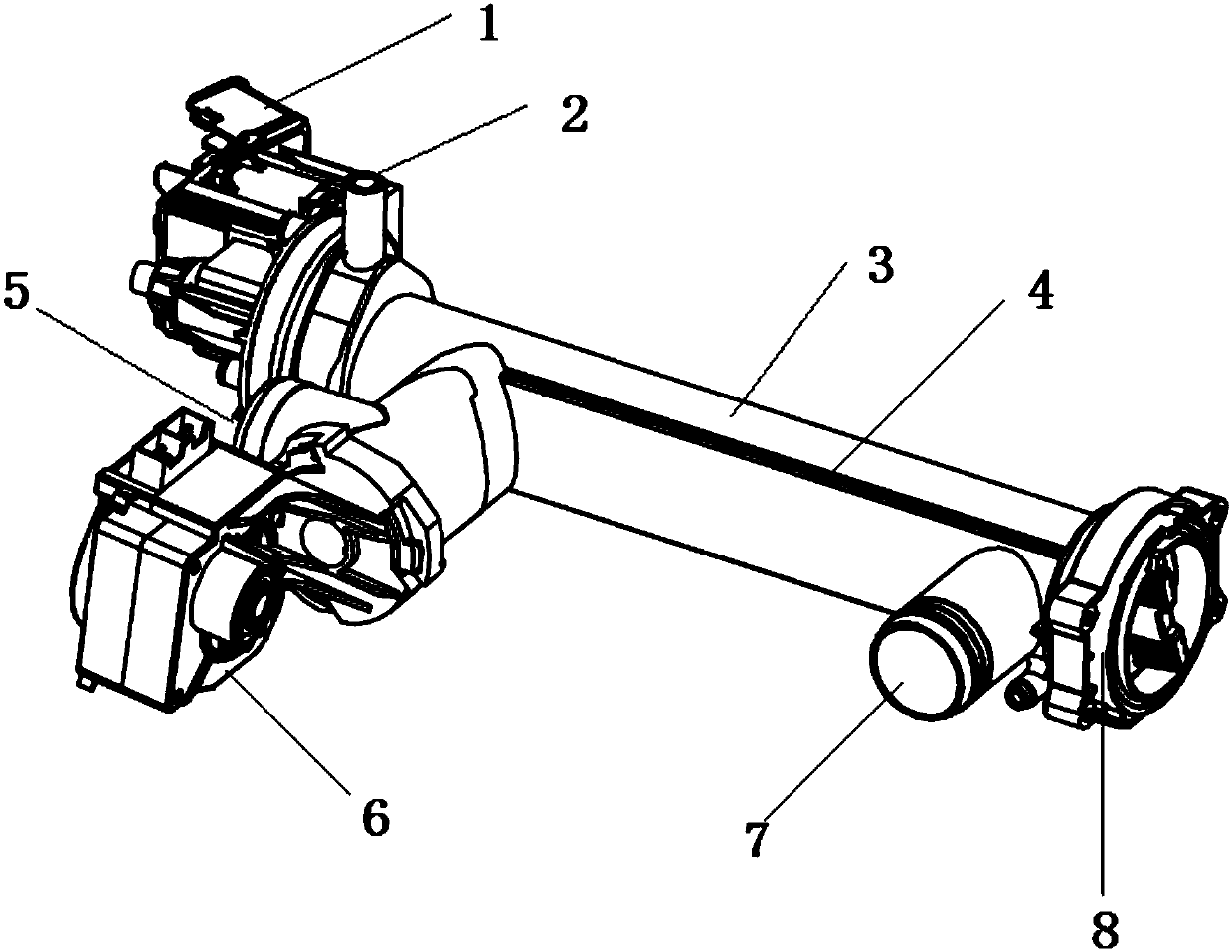
[0037] A drainage device includes a housing with a filter cavity 3, and a filter device 4 arranged in the filter cavity 3. The housing is provided with a water inlet 7, a circulating water outlet 2, and a drain 5, all of which can communicate with the filter cavity 3. The circulating water outlet 2 is connected with a circulating pump 1. The circulating pump 1 and the circulating water outlet 2 are arranged at one end of the housing, and the filter device 4 forms a first water path and a second water path in the filter cavity 3, and the first water path The purified water is filtered and the water is output from the circulating water outlet 2, and the second waterway drains and at the same time the filtered matter intercepted by the first waterway is discharged.
[0038] The housing has a cylindrical structure, the filter device 4 is arranged in the filter cavity 3 along the axial direction of the housing, the circulating water outlet 2 and the circulating pump 1 are arranged at t...
Embodiment 2
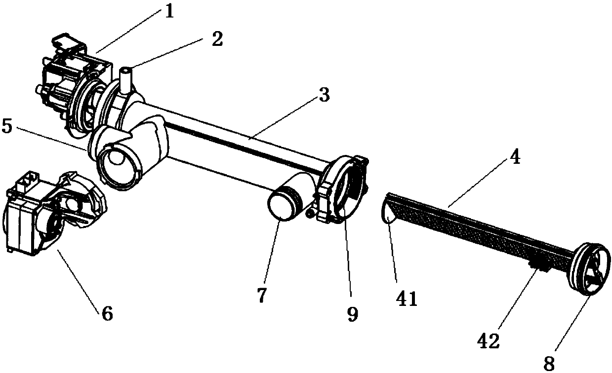
[0059] This embodiment is a further limited technical solution of the first embodiment. The housing includes a body and an end cover 8. One end of the body is provided with a mounting opening 9 which is provided with a cavity. The sheet-shaped filter device 4 is fixedly connected to the inner wall of the cavity and divides the cavity into Two fixed chambers.
[0060] The water inlet 7 and the water outlet 5 are located on the same side of the sheet-shaped filter device 4, and the circulating water outlet 2 is located on the other side. Therefore, the sheet-shaped filter device 4 can be fixedly connected to the inner wall of the cavity of the body to achieve separation. A waterway and a second waterway are separated in the chambers on both sides of the sheet-shaped filter device 4. It not only helps to increase the filtering path of the first waterway, but also facilitates the convenient discharge of the thread scraps trapped on the sheet surface of the filter device 4 along with...
Embodiment 3
[0081] This embodiment is limited to the technical solution of the first or second embodiment. The filter device 4 includes a filter part located in the center and a frame on the outer periphery. The frame is provided with a limiting groove, and the filter cavity 3 is provided with The limit groove corresponds to the guide rail, and the limit groove cooperates with the guide rail to fix the filter device 4.
[0082] The limit grooves on the frame and the guide rails cooperate to make the filter device 4 accurately and reliably arranged in the filter cavity 3, avoiding installation misalignment and causing the rinsing water containing thread chips to flow directly into the inner tub of the washing machine without being intercepted by the filter part .
[0083] The guide rail and the limiting groove cooperate and can slide relatively, so that the filter device 4 can be easily inserted into or drawn out of the filter cavity 3, and the installation and disassembly are more convenient. ...
PUM
 Abstract
Description
Claims
Application Information
 - R&D
- Intellectual Property
- Life Sciences
- Materials
- Tech Scout
- Unparalleled Data Quality
- Higher Quality Content
- 60% Fewer Hallucinations
Browse by: Latest US Patents, China's latest patents, Technical Efficacy Thesaurus, Application Domain, Technology Topic, Popular Technical Reports.
© 2025 PatSnap. All rights reserved.Legal|Privacy policy|Modern Slavery Act Transparency Statement|Sitemap|About US| Contact US: help@patsnap.com