
Injection tool and method to seal insert parts

A technology of inserting parts, injection molding and encapsulation, applied in the direction of coating, etc., can solve the problems of inability to completely seal and withstand high temperature, and achieve the effect of good sealing

Active Publication Date: 2019-05-07
ZF FRIEDRICHSHAFEN AG
View PDF7 Cites 0 Cited by
  • Summary
  • Abstract
  • Description
  • Claims
  • Application Information

AI Technical Summary

Problems solved by technology

The disadvantage of the hitherto known seals is that either they do not seal completely or, while providing a good seal, they cannot withstand the high temperatures involved in injection molding
Moreover, severe overspray (überspritzen) often occurs during injection molding, resulting in undesirable bulges

Method used


Image

  • Injection tool and method to seal insert parts
  • Injection tool and method to seal insert parts
  • Injection tool and method to seal insert parts

Examples


Embodiment Construction

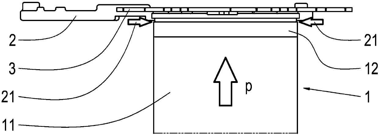
[0021] For the injection molding of inserts, thermosetting plastics are usually used as flowable materials, since they become very low-viscosity during the injection molding process and can therefore be used very well to fill thin-walled areas. However, it also tends to flow into areas that should not be overmolded, that is, where there should be no thermoset after injection molding is complete. These are, for example, electrical or electronic components, over which the thermosetting plastic flows during injection molding, since they are not completely sealed by the contact surfaces. This occurs because, due to manufacturing tolerances, there may be unevennesses in the insert, which cannot be completely sealed by the metal contact surfaces used hitherto. Flow into undesired areas necessitates costly reprocessing. This is especially a problem when injecting electrical or electronic components, since as little mechanical stress as possible is applied to these components in orde...


PUM


Abstract

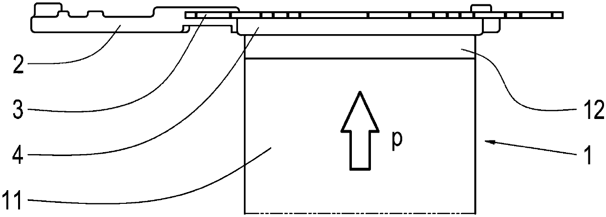
The invention relates to an injection tool and a method to seal insert parts; the injection tool comprises a base carrier 1 that is suitable to accommodate an insert part 2, wherein at least one separate part of the base carrier 1 forms a contact surface with the insert part 2 after it has been inserted into the base carrier 1, wherein at least the contact surface features a high-temperature material.

Description

technical field [0001] The invention relates to an injection molding tool and a method for sealing inserts. Background technique [0002] To protect the component, the component is usually provided with a cover and is injection-molded with a material that protects the component against the penetration of external influences. This occurs, for example, in injection molding tools. To this end, an insert, usually a sheet metal, is inserted into the cavity of the injection molding tool provided for this purpose. The insert is then injection-molded with a flowable plastic compound. During this process, the contact surfaces on the injection molding tool are used to seal the insert. The disadvantage of the hitherto known seals is that either they do not seal completely, or, while providing a good seal, they cannot withstand the high temperatures during injection molding. Furthermore, severe overspray frequently occurs during injection molding, whereby unwanted bulges form. Con...

Claims


Application Information

Patent Timeline
Patent Type & Authority Applications(China)
IPC IPC(8): B29C45/14B29K705/00
CPCB29C45/14418B29C2045/14934B29K2871/00B29C45/26B29C45/36B29C33/0044
Inventor 斯特凡·绍布马库斯·德里希
Owner ZF FRIEDRICHSHAFEN AG
Learn More