Laser device
A laser device, laser diode technology, applied in lasers, laser welding equipment, semiconductor lasers, etc., can solve problems such as beam leakage, and achieve the effect of reducing diameter
- Summary
- Abstract
- Description
- Claims
- Application Information
AI Technical Summary
Problems solved by technology
Method used
Image

Examples
Embodiment 1
[0042] Below, while referring to the attached Figure 1 A laser device according to an embodiment of the present invention will be described in detail.
[0043] (basic structure of the present invention)
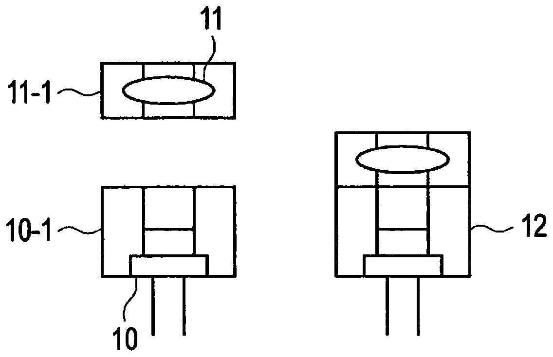
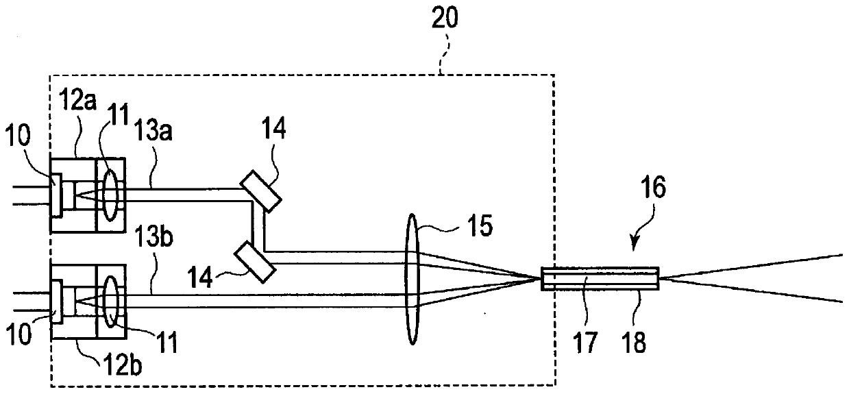
[0044] First, the basic configuration of the laser device of the present invention will be described. figure 1 It is a figure which shows the structure of the unit 12 which consists of the collimator lens holder 11-1 and the LD holder 10-1 in the laser apparatus concerning embodiment of this invention. figure 2 It is an overall configuration diagram of a laser device according to an embodiment of the present invention.
[0045] The laser device is equipped with: a plurality of laser diodes 10; a plurality of collimating lenses 11 (corresponding to the optical element of the present invention), which is set corresponding to the plurality of laser diodes 10; a plurality of units 12, which are connected to the plurality of laser diodes 10 is arranged correspondingly, is to f...
Embodiment 2
[0075] The spectral linewidth of the lateral multimode laser diode 10 is wider than the spectral linewidth of the lateral single-mode laser diode 10 . In applications requiring high intensity and narrow spectral linewidth, such as light sources for fluorescence excitation, it is necessary to improve the spectral linewidth. Therefore, the laser device according to the second embodiment of the present invention is characterized in that the spectral linewidth is improved by using an aperture member with a diffraction grating.
[0076] Figure 10 (a) is a diagram in which a diaphragm member 21 d with a diffraction grating is provided before the collimator lens 11 in the laser device according to Example 2 of the present invention. Figure 10 (b) is a diagram in which the aperture member 33 with a diffraction grating is provided after the collimator lens 11 in the laser device according to the second embodiment of the present invention.
[0077] Such as Figure 10 As shown in (a...
Embodiment 3
[0082] Figure 11 It is a configuration diagram of a laser device using a pinhole according to Example 3 of the present invention. Figure 11 The characteristic feature is that the laser device according to the third embodiment of the present invention is provided with a condenser lens 34 , a pinhole 35 , and a collimator lens 36 after the collimator lens 11 .
[0083] The condensing lens 34 condenses the light beam collimated by the collimator lens 11 to the hole PH formed in the pinhole 35 . Pinhole 35 utilizes hole PH to remove high M 2 ingredients, only take out the low M 2 Components are emitted to the collimator lens 36 . The collimating lens 36 is only for the low M 2 The components of the beam are collimated.
[0084] Thus, according to the laser device using the pinhole of the third embodiment, the same effect as that of the laser device of the first embodiment can be obtained.
PUM
 Abstract
Description
Claims
Application Information
 - R&D
- Intellectual Property
- Life Sciences
- Materials
- Tech Scout
- Unparalleled Data Quality
- Higher Quality Content
- 60% Fewer Hallucinations
Browse by: Latest US Patents, China's latest patents, Technical Efficacy Thesaurus, Application Domain, Technology Topic, Popular Technical Reports.
© 2025 PatSnap. All rights reserved.Legal|Privacy policy|Modern Slavery Act Transparency Statement|Sitemap|About US| Contact US: help@patsnap.com