
Switch cabinet installation base and switch cabinet

A technology for installing bases and switch cabinets, which is applied to the details of substation/switch layout, substation/distribution device housing, electrical components, etc., can solve the problem of low installation efficiency, and achieve the effect of improving efficiency, reducing welding operations, and simplifying operation.

Pending Publication Date: 2019-05-03
TIANJIN HUIHE ELECTRICAL EQUIP
View PDF0 Cites 0 Cited by
  • Summary
  • Abstract
  • Description
  • Claims
  • Application Information

AI Technical Summary

Problems solved by technology

[0003] At present, when installing the switchgear, it is usually necessary to use reinforced concrete to pour the base first, and then install the switchgear after a period of time is formed, and the installation efficiency is low

Method used


Image

  • Switch cabinet installation base and switch cabinet
  • Switch cabinet installation base and switch cabinet
  • Switch cabinet installation base and switch cabinet

Examples


Embodiment 1

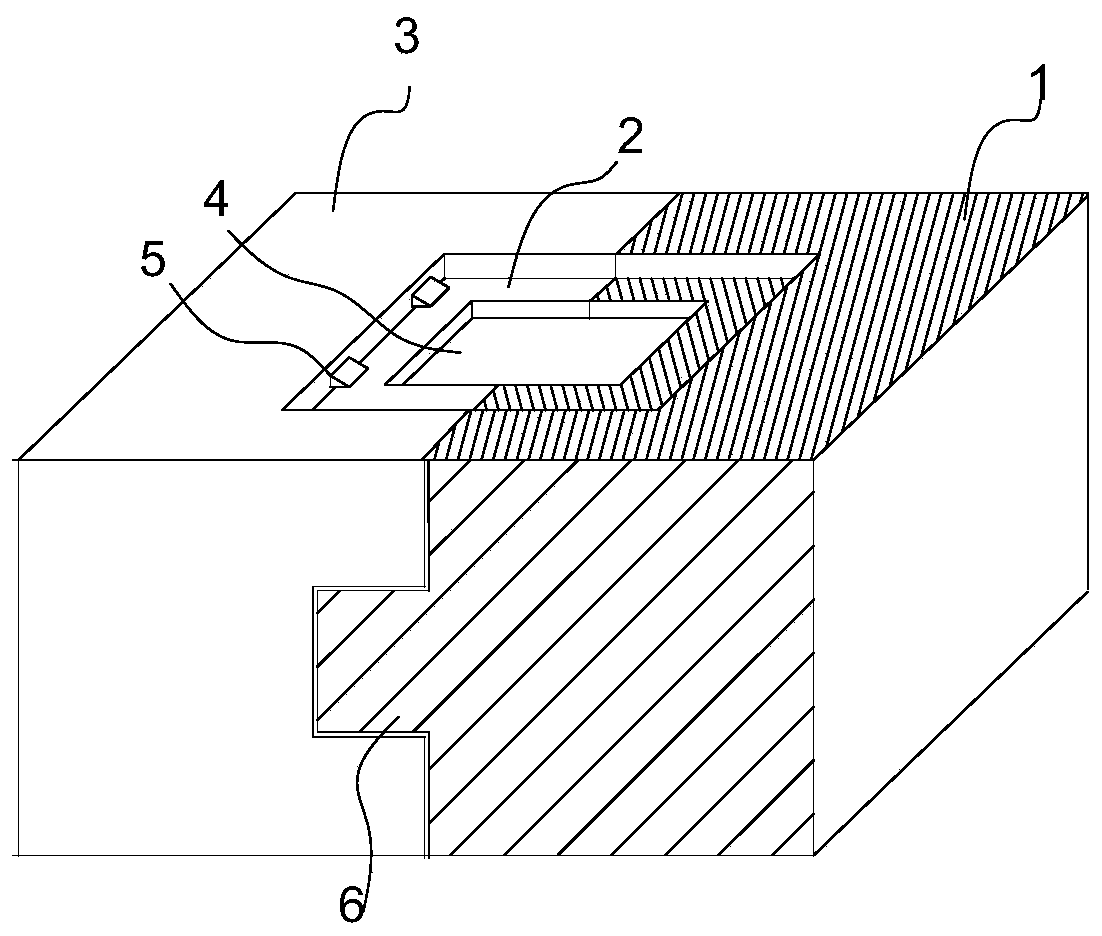
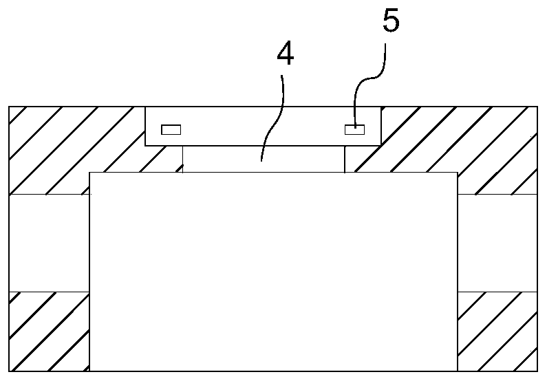
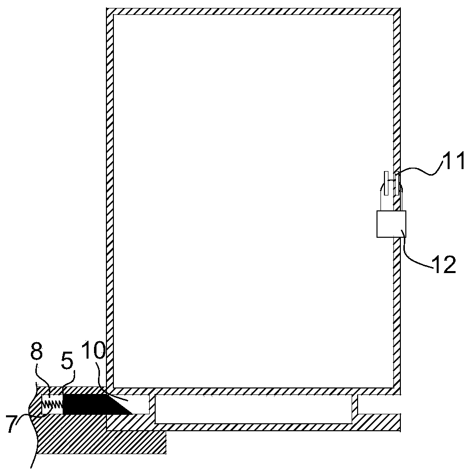
[0024] Such as Figure 1-4 As shown, the technical solution adopted in the present invention is: a switch cabinet installation base, including: a left base body and a right base body used in conjunction with each other, and the left base body and the right base body are connected left and right, The inside of the two forms a cavity, and the upper end surface forms an installation groove. The middle part of the installation groove is provided with a communication opening that communicates with the cavity. The side wall of the installation groove is provided with a telescopic locking block. The lower end is set in the installation groove, and the lower end of the switch cabinet body is provided with a card slot. After installation, the locking block is stuck in the card slot, and the locking block is arranged in a laterally arranged sliding cavity on the installation base. Inside, one end of the spring is connected to the inside of the sliding cavity, and the other end of the sp...


PUM


Abstract

The invention discloses a switch cabinet installation base, which comprises a left side base body and a right side base body which are used in cooperation, wherein the left side base body and the right side base body are connected in a left-right splicing manner, a cavity is formed inside the left side base body and the right side base body, and an installation groove is formed in the upper end surfaces. Accordingly, the invention further discloses a switch cabinet, which comprises the switch cabinet installation base. The switch cabinet comprises a switch cabinet body, wherein the lower end of the switch cabinet body is arranged in the installation groove, clamping grooves are formed in the lower end of the switch cabinet body, locking blocks are clamped in the clamping grooves after installation, and the locking blocks can achieve the self-locking effect of the switch cabinet body without welding the switch cabinet body to the installation base. The operation is simple, the welding operation is omitted, the efficiency is improved, and the environment is protected; and by arranging the prefabricated installation base, the installation efficiency is further improved.

Description

technical field [0001] The invention belongs to the technical field of switch cabinet production, and in particular relates to a switch cabinet installation base and a switch cabinet. Background technique [0002] The switch cabinet is a kind of electrical equipment. The outside line of the switch cabinet first enters the main control switch in the cabinet, and then enters the sub-control switch. Each branch is set according to its needs. The main function of the switchgear is to open and close, control and protect electrical equipment during the process of power generation, transmission, distribution and power conversion in the power system. The components in the switch cabinet are mainly composed of circuit breakers, disconnectors, load switches, operating mechanisms, transformers and various protection devices. [0003] At present, when installing the switchgear, it is usually necessary to use reinforced concrete to pour the base first, and then install the switchgear af...

Claims


Application Information

Patent Timeline
Patent Type & Authority Applications(China)
IPC IPC(8): H02B1/30H02B1/50
Inventor 孙巨岗
Owner TIANJIN HUIHE ELECTRICAL EQUIP
Learn More