Lifting wood stove

A firewood stove, lifting technology, applied in the field of liftable firewood stove, can solve the problems of insufficient supply of oxygen, failure to achieve effective energy saving, failure to achieve effective combustion, etc., so as to be easy to carry out, improve combustion thermal efficiency, and improve efficiency Effect

Pending Publication Date: 2019-05-03
吴玉新
View PDF0 Cites 0 Cited by
  • Summary
  • Abstract
  • Description
  • Claims
  • Application Information

AI Technical Summary

Problems solved by technology

[0002] At present, there are firewood stoves used for cooking food in the wild in the prior art, including small and slightly larger ones. Among them, the smaller ones are convenient for users to carry, but they often cannot meet the needs of users for outdoor dining at one time. It can only be cooked once, and due to the limitation of its volume, the sufficient supply of oxygen cannot be realized, so that it cannot achieve the purpose of effective combustion during use; the disadvantages of some larger wood-fired stoves in the prior art are that It is inconvenient to carry, and there are still disadvantages in the process of burning that the windproof effect is poor, and the purpose of effective energy saving cannot be achieved

Method used


Image

  • Lifting wood stove
  • Lifting wood stove
  • Lifting wood stove

Examples


Embodiment Construction

[0025] The present invention will be described in further detail below in conjunction with the accompanying drawings.

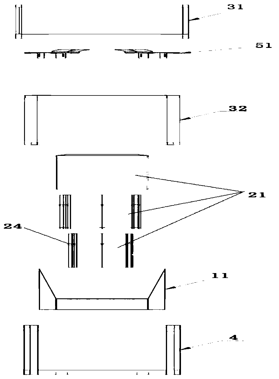
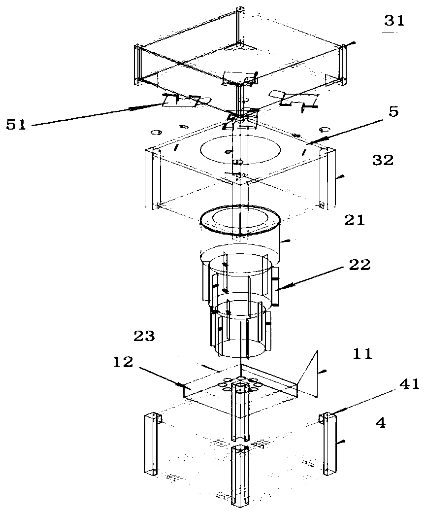
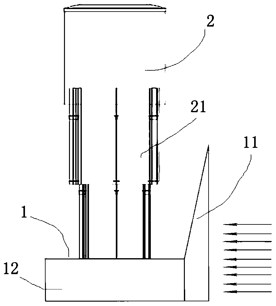
[0026] combined with Figure 1~3 , a liftable firewood stove, including a suction part 1, a combustion chamber 2, and a windshield 3 arranged sequentially from bottom to top, and also includes a lifting bracket 4 outside, wherein,

[0027] The air suction part 1 includes a tuyere part 11 with a lateral opening, and a lower drain part 12 communicating with the other end of the tuyere part 11, which is used to make the air entering the tuyere part 11 circulate to the lower drain part 12, and then realize the air entering through the lower drain part 12. To the combustion chamber 2 to support combustion;

[0028] The combustion chamber 2 includes a number of combustion units 21 stacked and nested in sequence. A slag plate 23 is embedded in the combustion unit 21 at the lowermost end of the combustion chamber 2. The combustion chamber 2 is used to accommodate fu...


PUM


Abstract

The invention relates to a lifting wood stove. The lifting wood stove comprises an air suction part, a combustion chamber and an air proofing cover which are arranged in sequence from bottom to top, and the lifting wood stove further comprises a lifting bracket covering the exterior. The air suction part comprises an air opening part with a lateral opening, and a lower leakage part communicating with the other end of the air opening part; the combustion chamber comprises a plurality of combustion units which are overlapped sequentially and connected in a sleeving mode, and slag leakage platesare embedded at the positions, in the combustion units, of the lowermost end of the combustion chamber; the air proofing cover comprises a hexahedral frame, air baffles are arranged on the left side face, the rear side face and the right side face of the frame correspondingly, the front side face, the upper end face and the lower end face of the frame are all in a hollowed-out state, and the lowerend face of the frame communicates with the upper end of the combustion chamber; and the lifting bracket comprises the hexahedral frame composed of a plurality of lifting rods, wherein the air suction part is located in a rectangular frame and connected with the bottom end of the rectangular frame, and the lower end of the air proofing cover is connected with the upper end of the rectangular frame. The lifting wood stove is convenient to carry and high in combustion efficiency and can be widely applied to the technical field of combustion equipment.

Description

technical field [0001] The invention relates to the technical field of combustion equipment, in particular to a liftable firewood stove. Background technique [0002] At present, there are firewood stoves used for cooking food in the wild in the prior art, including small and slightly larger ones. Among them, the smaller ones are convenient for users to carry, but they often cannot meet the needs of users for outdoor dining at one time. It can only be cooked once, and due to the limitation of its volume, the sufficient supply of oxygen cannot be realized, so that it cannot achieve the purpose of effective combustion during use; the disadvantages of some larger wood-fired stoves in the prior art are that Inconvenient to carry, and the shortcoming that also exists in the process of burning is that windproof effect is poor, and can't reach the purpose of effective energy saving. [0003] Therefore, a kind of firewood stove that is easy to carry, high combustion heat efficiency...

Claims


Application Information

Patent Timeline
Patent Type & Authority Applications(China)
IPC IPC(8): F24B1/02F24B1/08F24B13/00
Inventor 吴玉新
Owner 吴玉新
Why Eureka
Try Eureka