
Proximal tibia osteotomy device

A technique for tibia and osteotomy, which is used in bone drill guidance, medical science, surgery, etc., and can solve problems such as the effect of joint replacement surgery, affecting the quality of life of patients, and poor accuracy.

Pending Publication Date: 2019-05-03
XIANGYA HOSPITAL CENT SOUTH UNIV
View PDF0 Cites 10 Cited by
  • Summary
  • Abstract
  • Description
  • Claims
  • Application Information

AI Technical Summary

Problems solved by technology

The current traditional alignment method is mechanical axis alignment, that is, osteotomy and prosthesis installation are performed according to the mechanical axis of the lower limb formed by the center of the femoral head-knee joint center-ankle joint center. The axis of rotation is perpendicular to the mechanical axis without inclination, but with this alignment technique, the axis of rotation formed is inconsistent with the axis of motion of the individual knee joint of the patient. Therefore, after total knee arthroplasty, the patient cannot fully recover the axis of motion of the physiological motion, which may It will affect the effect of joint replacement surgery, and then affect the follow-up quality of life of patients; in order to solve the above problems, the dynamic alignment theory has emerged in recent years, that is, to perform osteotomy and install prosthesis according to the individual knee joint movement axis of the patient. It is hoped that the patient's axis of motion can be fully restored, but the human tibia is inherently varus, so according to the dynamic alignment theory, the tibia should also be kept in varus for osteotomy, and the current surgical device requires manual adjustment of the osteotomy The inversion angle of the module is realized, and the accuracy is poor

Method used


Image

  • Proximal tibia osteotomy device
  • Proximal tibia osteotomy device
  • Proximal tibia osteotomy device

Examples


Embodiment Construction

[0021] In order to better understand the present invention, the invention will be described in further detail below in conjunction with the accompanying drawings and implementation examples, but the embodiments of the present invention are not limited thereto, and the scope of protection of the present invention also relates to those skilled in the art who can achieve according to the concept of the present invention. Think of the equivalent technical means.

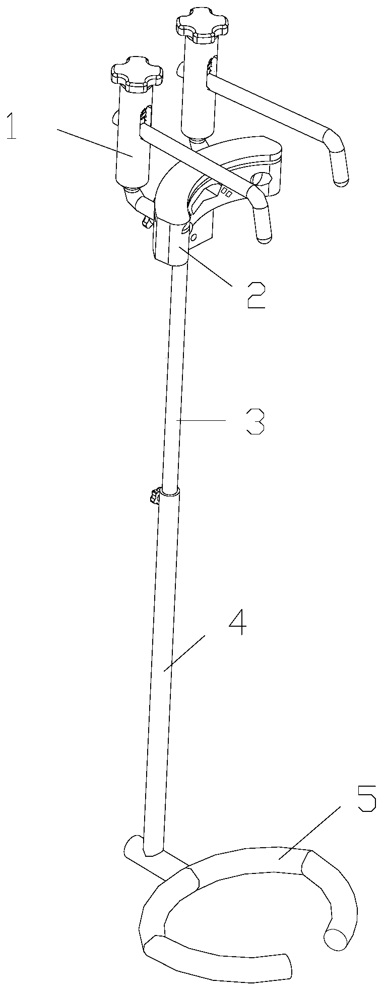
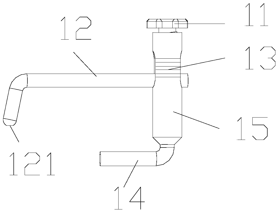
[0022] Such as Figures 1 to 4 As shown, a proximal tibial osteotomy device includes a connecting rod 3 with a pointer installed on the connecting rod 4 of the condyle holder, a tibial osteotomy guide 2 installed on the connecting rod 3 with a pointer, and a tibial osteotomy guide installed on the connecting rod 4 Two osteotomy thickness limiters 1 on 2,

[0023] The tibial osteotomy guide plate 2 includes a tibial fixation plate 26 matching the radian of the tibia and a connecting plate 25 fixed on the tibial fixing pl...


PUM


Abstract

The invention relates to a proximal tibia osteotomy device. The device includes a connecting rod with a pointer mounted on a condyle-holding device connecting rod, a tibia osteotomy guide plate mounted on the connecting rod with the pointer, and two osteotomy thickness restrictors mounted on the tibia osteotomy guide plate, the tibia osteotomy guide plate comprises a tibial fixing plate matching with the curvature of the tibia and a connecting plate fixed on the tibial fixing plate, the connecting plate and the pointer end of the connecting rod with the pointer are connected by a pressure screw so as to enable the connecting plate to rotate relative to the connecting rod with the pointer, the tibia fixing plate is provided with an osteotomy saw blade guiding groove, positioning circular holes and nail holes, and the two positioning circular holes are formed in the tibia fixing plate with central symmetry along the center line of the long side of the osteotomy saw blade guiding groove.The device is convenient to adjust, and can determine and limit the thickness of the osteotomy in the vertical direction when the tibia osteotomy guide plate is varus. The osteotomy angle is the physiological varus and valgus angle of the patient, and the device realizes the dynamic alignment of the knee arthroplasty, and facilitates rapid recovery of the patient in order to improve the satisfaction for the knee joint activity of the patient after the replacement.

Description

technical field [0001] The invention relates to a proximal tibial osteotomy device. Background technique [0002] Total knee arthroplasty is a widely used and highly effective treatment for patients with advanced knee disease. Alignment technique is the basis of knee arthroplasty, which refers to the method of osteotomy and prosthesis installation according to the alignment during arthroplasty. The current traditional alignment method is mechanical axis alignment, that is, osteotomy and prosthesis installation are performed according to the mechanical axis of the lower limb formed by the center of the femoral head-knee joint center-ankle joint center. The axis of rotation is perpendicular to the mechanical axis without inclination, but with this alignment technique, the axis of rotation formed is inconsistent with the axis of motion of the individual knee joint of the patient. Therefore, after total knee arthroplasty, the patient cannot fully recover the axis of motion of t...

Claims


Application Information

Patent Timeline
IPC IPC(8): A61B17/16A61B17/17
Inventor 谢杰刘东昊胡懿郃曾敏蒋其宏朱剑熹
Owner XIANGYA HOSPITAL CENT SOUTH UNIV
Learn More