
Three-phase three-dimensional stacked iron core structure

A stacked iron core, three-dimensional technology, applied in the field of three-phase three-dimensional stacked iron core structure, can solve the problems of high no-load loss process coefficient, low filling coefficient, long manufacturing period, etc., achieve simple performance control measures, reduce material consumption, The effect of simple manufacturing process

Pending Publication Date: 2019-04-30
TBEA SHENYANG TRANSFORMER GRP CO LTD
View PDF8 Cites 0 Cited by
  • Summary
  • Abstract
  • Description
  • Claims
  • Application Information

AI Technical Summary

Problems solved by technology

[0008] In view of the prior art, the production process of the trapezoidal closed three-dimensional coil core requires special equipment, strict process control requirements, and a long manufacturing period; the folding process of the trapezoidal open folded three-dimensional iron core structure requires special equipment, and the process coefficient of no-load loss is too high , product package, and inserting pieces are difficult; and the filling coefficient of the cross-section of the rectangular material laminated three-dimensional iron core structure is too low, and the laminations need to be sharpened. The problem to be solved by the present invention is to provide a stacking, rolling Combined cutting three-phase three-dimensional stacked iron core structure

Method used


Image

  • Three-phase three-dimensional stacked iron core structure
  • Three-phase three-dimensional stacked iron core structure
  • Three-phase three-dimensional stacked iron core structure

Examples


Embodiment Construction

[0033] The present invention will be further elaborated below in conjunction with the accompanying drawings of the description.

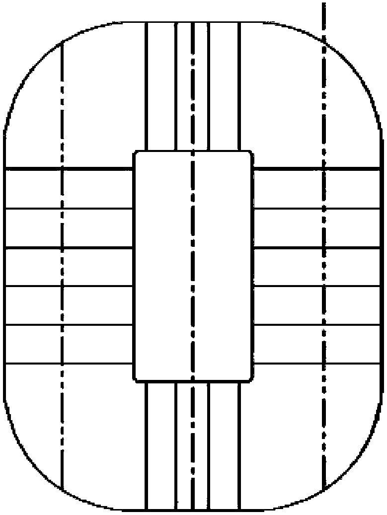
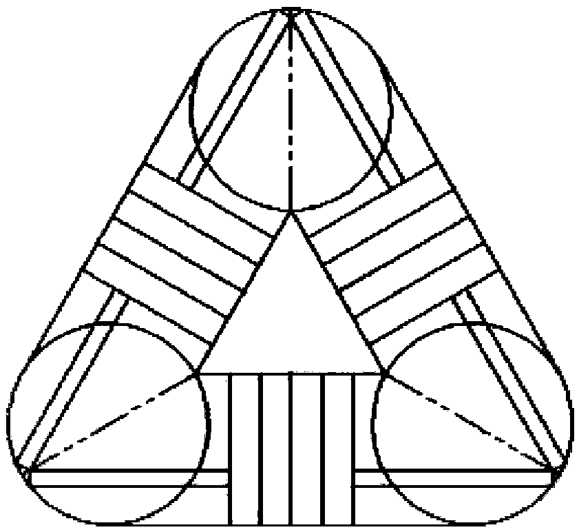
[0034] Such as Figures 4A-4C As shown, the present invention is a stacked and rolled combined type cutting three-phase three-dimensional stacked iron core structure. The semicircular iron core section formed by combining the trapezoidal material stacked part 1 and the rectangular material stacked part 2 is used as the core unit Frame 3, the three iron core single frames 3 are spliced ​​in pairs in the vertical direction to form a three-dimensional iron core.

[0035] The stacked part 1 of the trapezoidal material adopts the longitudinal oblique line cutting of the rolled iron core, and then cuts horizontally according to the design angle and the length of the single silicon steel sheet to form multiple single silicon steel sheets, which are composed of multiple single silicon steel sheets in a stacked form The cross-section is trapezoidal stage, a...


PUM


Abstract

The invention relates to a three-phase three-dimensional stacked iron core structure. A semicircular iron core section formed by combining a trapezoidal material stacking part and a rectangular material stacking part is taken as an iron core single frame; three iron core single frames are spliced with each other in a vertical direction so that a three-dimensional iron core can be formed; the trapezoidal material stacking part adopts a roll-core to perform longitudinal oblique line cutting, and transverse shearing can be performed according to design angles and the length of a single silicon steel sheet so that multiple single silicon steel sheets can be formed; the multiple single silicon steel sheets can form a stage whose section is in a trapezoidal shape by adopting a stacking form; andthe multiple same or different trapezoidal stages can form the trapezoidal material stacking part whose section is stacked by the multiple trapezoidal stages by adopting the stacking form again. Thus, the section filling coefficient of the iron core can be increased; a stepping structure is adopted between single layers or multilayers, a three-phase three-dimensional stacked iron core can be formed by multilayers of square-shaped iron core sheets, so that iron core winding equipment can be saved; and the three-phase three-dimensional stacked iron core structure having three iron core columnswhose cross sections are in circular shapes can be formed through the stepping structure adopted between the single layers or the multilayers.

Description

technical field [0001] The invention relates to a transformer core structure, in particular to a three-phase three-dimensional laminated core structure. Background technique [0002] At present, the iron core cutting methods of three-phase three-dimensional wound cores in China include trapezoidal material closed three-dimensional wound core structure, trapezoidal material open folded three-dimensional iron core structure and rectangular material laminated three-dimensional iron core structure. [0003] Such as Figure 1A ~ 1C As shown, the trapezoidal material closed wound core is the traditional structure of the three-dimensional wound core transformer. It is formed by winding trapezoidal material strips of several specifications in sequence. The silicon steel strips are tightly wound and the iron core has a large filling area. However, the traditional winding machine cannot meet the requirements of this process. It is necessary to purchase special winding equipment, and t...

Claims


Application Information

Patent Timeline
Patent Type & Authority Applications(China)
IPC IPC(8): H01F27/26H01F27/245
CPCH01F27/245H01F27/266
Inventor 金宝高键张玲
Owner TBEA SHENYANG TRANSFORMER GRP CO LTD
Learn More