Tumbling type roller coaster device

A technology for roller coasters and driving devices, which is applied in entertainment devices, entertainment, slideways, etc., can solve the problems of increasing costs, increasing equipment operating costs, and long construction periods, and improving the frequency of track changes, reducing operation and maintenance costs. The effect of rapid rate changes

Active Publication Date: 2019-04-30
北京中冶设备研究设计总院有限公司
View PDF7 Cites 2 Cited by
  • Summary
  • Abstract
  • Description
  • Claims
  • Application Information

AI Technical Summary

Problems solved by technology

However, with the innovation of technology and the continuous improvement of passengers' requirements for riding experience, the earlier roller coaster device has a small speed change rate, a single track design, and mostly straight-line driving, which is difficult to meet the new requirements brought about by technological innovation and development. requirements
[0005] In view of the problems existing in the above-mentioned earlier technologies, a roller coaster device with complex track design, many track changes, fast speed changes and frequent track rollovers is proposed in the prior art, in order to meet the new requirements of technological innovation and development and passengers' ride experience. Require
However, the multi-tumbling track roller coaster device in the prior art needs to occupy a large area in space and in the plane due to its complex track design, and the construction is difficult and the construction period is long. Expansion greatly increases the cost of construction
On the other hand, due to the long track stroke of this new roller coaster device proposed in the prior art, under the existing conditions, because there is only one train running on the track at the same time, the utilization rate of equipment and track is low, and the equipment operation is further increased. cost

Method used


Image

  • Tumbling type roller coaster device
  • Tumbling type roller coaster device
  • Tumbling type roller coaster device

Examples


Embodiment Construction

[0021] Embodiments of the rolling roller coaster device according to the present invention will be described below with reference to the accompanying drawings. As those skilled in the art would realize, the described embodiments may be modified in various different ways, all without departing from the spirit and scope of the present invention. Accordingly, the drawings and description are illustrative in nature and not intended to limit the scope of the claims. Also, in this specification, the drawings are not drawn to scale, and like reference numerals denote like parts.

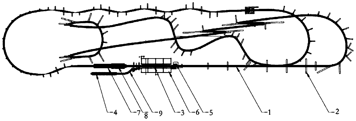
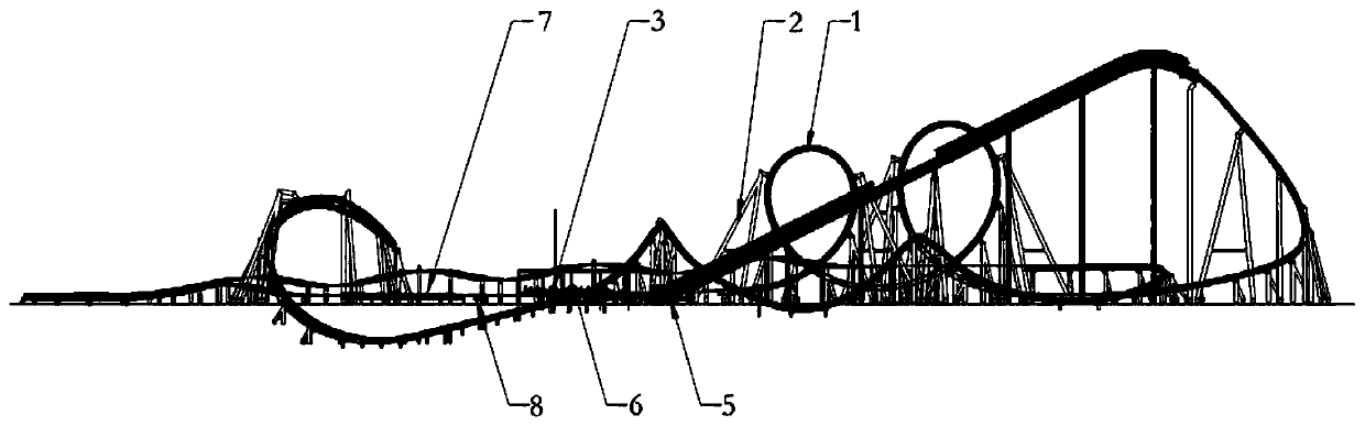
[0022] figure 1 It is a top view, showing the top view structure of the rolling roller coaster device described in one embodiment of the present invention. figure 2 is a side view, showing the figure 1 Side-view structure of the roller coaster rig shown. Such as figure 1 with figure 2 As shown, the rolling roller coaster device described in this embodiment of the present invention includes a track 1...


PUM


Abstract

The invention provides a tumbling type roller coaster device. The tumbling type roller coaster device comprises tracks, upright columns for supporting the tracks, a train running on the tracks, a traction device used for pulling the train to travel, a station allowing parking of the train and a driving device for driving, wherein the tracks comprise a continuous vertical ring track, a horse-shoe collar track and spiral tracks. The tracks comprise the continuous vertical ring track, the horse-shoe collar track, first spiral tracks, second spiral tracks and a third spiral track, by means of thecontinuous vertical ring track and the horse-shoe collar track, utilization of track space can be increased on the premise that the track rangeability is met, and the requirements for high change rateand fast train rate change can be met by track design through the tumbling form; correspondingly, a plurality of first spiral tracks and a plurality of second spiral tracks are distributed sequentially according to different helicity and different track lengths, so that the track change frequency can be further increased on the premise that the overall floor area of the track device is reduced.

Description

technical field [0001] The invention relates to the technical field of large amusement facilities, in particular to a rolling roller coaster device. Background technique [0002] Large roller coasters are common amusement facilities in large amusement parks, which mainly include trains, driving tracks, columns, traction systems and braking systems. The operating principle of the roller coaster is that the traction system pulls the train to the highest point of the running track, and then the traction system is separated from the train, and then the train runs quickly along the running track under the action of its own gravity and inertia, relying on the mutual transformation of its own potential energy and kinetic energy , and finally the braking system operates, causing the train to decelerate and return to the station. [0003] The roller coaster device as a whole usually includes platforms for docking trains, rails and columns supporting the rails, traction systems, driv...

Claims


Application Information

Patent Timeline
Patent Type & Authority Applications(China)
IPC IPC(8): A63G21/04A63G21/10
CPCA63G21/04A63G21/10
Inventor 黄羽王国平师学斌张金利孟洁孙亚伟牟世学
Owner 北京中冶设备研究设计总院有限公司
Why Eureka
Try Eureka