Integrated plug-in head

A plug-in head and component technology, which is applied in the direction of electrical components, electrical components, electrical components to assemble printed circuits, etc., can solve the problems of small application range, low plug-in efficiency, inconvenient control, etc., and achieve convenient and reliable control, simple structure, Easy to control effects

Pending Publication Date: 2019-04-26
ZHUHAI ZHIXIN AUTOMATIC TECH CO LTD
View PDF0 Cites 0 Cited by
  • Summary
  • Abstract
  • Description
  • Claims
  • Application Information

AI Technical Summary

Problems solved by technology

[0003] With the development of the current plug-in industry, the components required for plug-in are getting smaller and smaller. Because the split plug-in head is too large, it is inconvenient to move.
Obviously, the above-mentioned split plug-in head obviously cannot meet the plug-in requirements of this type of components.
For this reason, some companies have introduced integrated control plug-in heads, which generally adopt unified rotation or lifting, differential lifting or rotation control methods, and even some integrated plug-in heads achieve unified lifting and rotation, but this type of plug-in machine is easy to move with the circuit board Interference makes the scope of use of this kind of dual unified side very small, generally only used in special plug-in occasions
As for the remaining two types of plug-in machines, due to the unification of rotation or lifting, the movement of a single clamping head is not smooth and the control is inconvenient. When the entire plug-in head realizes differential plug-in, the overall plug-in efficiency is low.

Method used


Image

  • Integrated plug-in head
  • Integrated plug-in head
  • Integrated plug-in head

Examples


Embodiment Construction

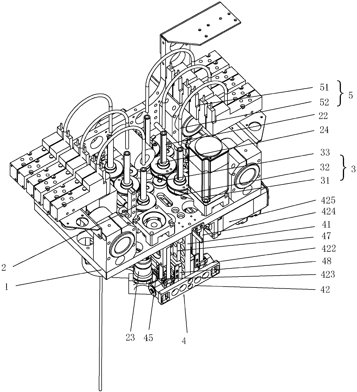
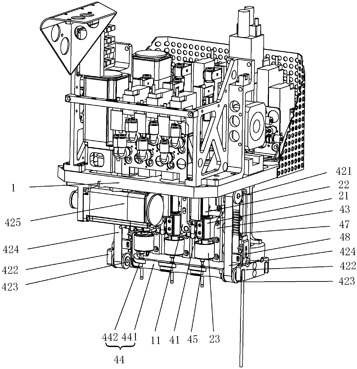
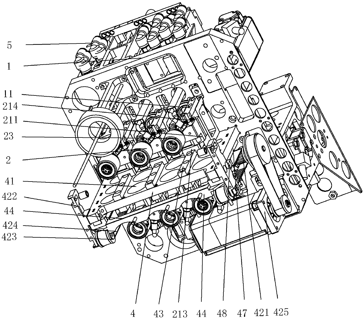
[0028] see Figure 1 to Figure 9 , an integrated plug-in head of the present invention, including a mounting base 1, a clamping assembly 2 movably mounted on the mounting base 1, a rotating group 3, and a lifting group 4 for controlling the lifting of the clamping assembly 2, said The lifting group 4 includes a lifting frame 41 installed on the bottom of the installation base 1, a cross bar 44 that can slide vertically on the lifting frame 41, and a lifting member 42 for driving the cross bar 44 to move. The clamping assembly 2 is set There are several groups, and they are arranged side by side on the front side and / or the rear side of the lifting frame 41. The rotating group 3 can drive all the clamping components 2 on the same side to rotate synchronously. The lifting frame 41 corresponds to each group of clamping components 2 Each set of clamping components 2 is slidably mounted on the corresponding vertical rail 43 through the locking member 21, and the cross bar 44 is pro...


PUM


Abstract

The invention discloses an integrated plug-in head. The integrated plug-in head comprises an installation base, multiple clamping components movably installed on the installation base, a rotating group and a lifting group for controlling rising and falling of the clamping components, the lifting group comprises a lifting frame installed at the bottom of the installation base, a cross bar slidablyinstalled on the lifting frame and a lifting member used for driving the cross bar to move, the clamping components are arranged on the front side and/or the rear side of the lifting frame side by side, the rotating group can drive all clamping components on the same side to rotate synchronously, vertical rails are arranged at the positions, corresponding to the clamping components, of the liftingframe respectively, each clamping component is slidably installed on the corresponding vertical rail through a locking member, a clamping position is arranged on the portion, corresponding to each clamping component, of the cross bar, and the lifting member can drive the clamping components to rise and fall by means of cooperation of the clamping positions and the locking members. The whole plug-in head is simple in structure and convenience to control, each clamping component can achieve differential movement, and overall control is convenient and reliable.

Description

technical field [0001] The invention relates to the technical field of plug-in machines, in particular to an integrated plug-in head. Background technique [0002] At present, the plug-in head on the plug-in machine basically adopts a split control method, that is, each clamping head is equipped with a lifting and rotating mechanism at the same time, and each clamping head is controlled separately. The advantage of this is that a single clamping head The control is simple, and different plug-ins can be realized, and the number of clamping heads can be increased or decreased according to the demand to adapt to different plug-in strength requirements. However, this type of plug-in machine is composed of a plurality of separate clamping heads, which makes the control system of the entire plug-in machine very large and large in size, which in turn causes the momentum of the entire plug-in head to be large when it moves, and the vibration of the entire plug-in machine is large. ...

Claims


Application Information

Patent Timeline
Patent Type & Authority Applications(China)
IPC IPC(8): H05K13/04H05K3/30
CPCH05K3/30H05K13/0404
Inventor 冯艳生范秀广严炜张凡林锡宁林森明罗建明刘卫李天玉
Owner ZHUHAI ZHIXIN AUTOMATIC TECH CO LTD
Why Eureka
Try Eureka