
An automatic retractable vortex generator system based on wind turbine blades

A technology of vortex generators and wind turbine blades, which is applied to wind turbines, wind turbines, and wind power generation in the same direction as the wind. It can solve problems such as resistance, complex wind turbine power generation environment, and increased load on wind turbine blades.

Active Publication Date: 2020-03-17
UNIV OF SHANGHAI FOR SCI & TECH
View PDF5 Cites 0 Cited by
  • Summary
  • Abstract
  • Description
  • Claims
  • Application Information

AI Technical Summary

Problems solved by technology

[0003] However, the passively controlled vortex generators in the prior art will bring a certain amount of aerodynamic resistance to the wind turbine blades, that is, when the wind turbine blades do not have flow separation, the existence of the vortex generators will affect the distribution of the original flow field, thereby affecting the flow of the wind turbine blades. Some scholars have proposed an actively controlled vortex generator, which can allow the vortex generator to freely enter and exit the surface of the blade according to the operating state of the wind turbine blade, while ensuring the better aerodynamic performance of the wind turbine blade. The resistance produced by the vortex generators on the blades of the wind turbine in the non-stall state
[0004] Some scholars set flaps on the trailing edge of the blades that can be deflected according to the wind force, and can transmit the movement of the flaps to the vortex generators, so as to realize the synchronous movement of the two and achieve the purpose of automatic lifting of the vortex generators. The flaps on the blades need to be driven by relevant electric devices, and the expansion and contraction of the vortex generators cannot be flexibly changed according to whether flow separation occurs on the blade surface
In an environment with unstable wind power, the load on the blades of the wind turbine will be increased intermittently and irregularly, making the power generation environment faced by the wind turbine more complicated.
Therefore, the problems in the prior art are as follows: although the vortex generator can suppress the flow separation when the airfoil has a large angle of attack, it becomes an unnecessary device when the angle of attack is small, which will not only reduce the lift coefficient Small and creates additional drag

Method used


Image

  • An automatic retractable vortex generator system based on wind turbine blades
  • An automatic retractable vortex generator system based on wind turbine blades
  • An automatic retractable vortex generator system based on wind turbine blades

Examples


Embodiment Construction

[0031] The automatic retractable vortex generator system based on wind turbine blades of the present invention will be described in more detail below in conjunction with the schematic diagram, wherein a preferred embodiment of the present invention is represented, and it should be understood that those skilled in the art can modify the present invention described here, and The advantageous effects of the invention are still achieved. Therefore, the following description should be understood as the broad knowledge of those skilled in the art, but not as a limitation of the present invention.

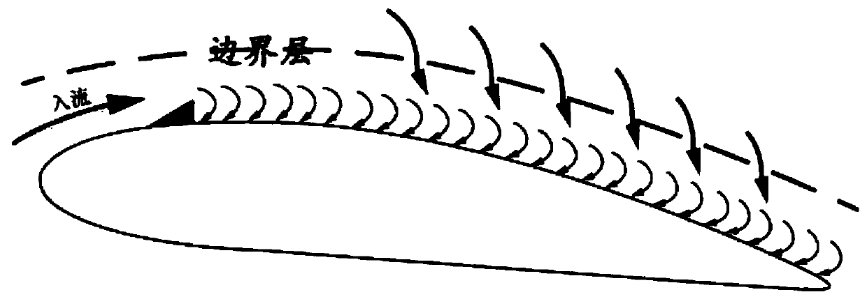
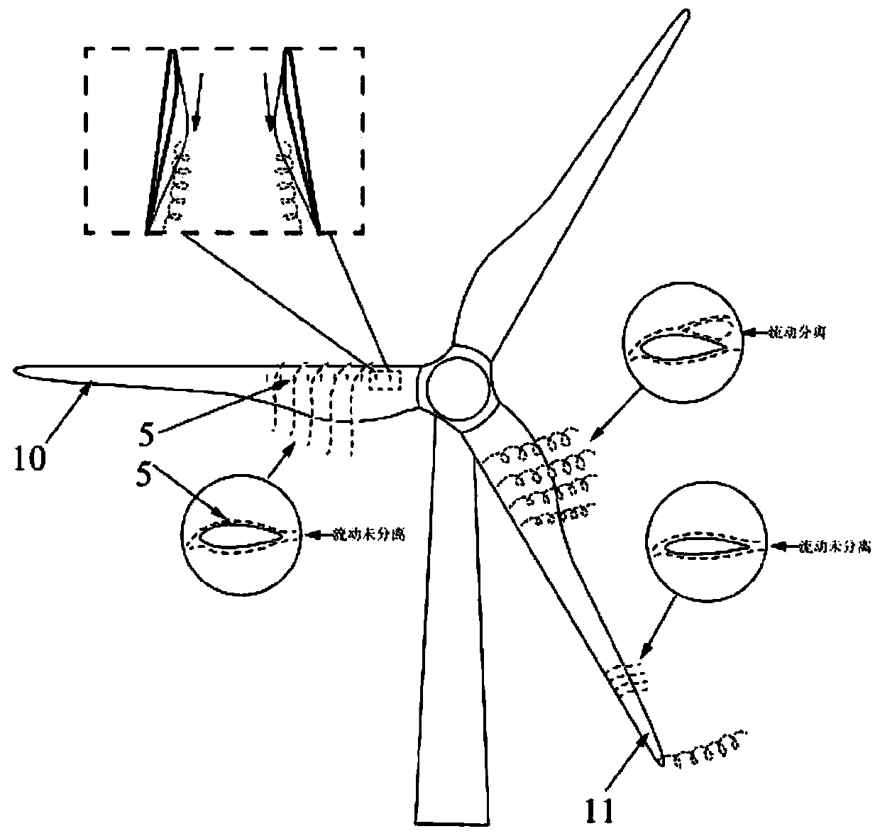
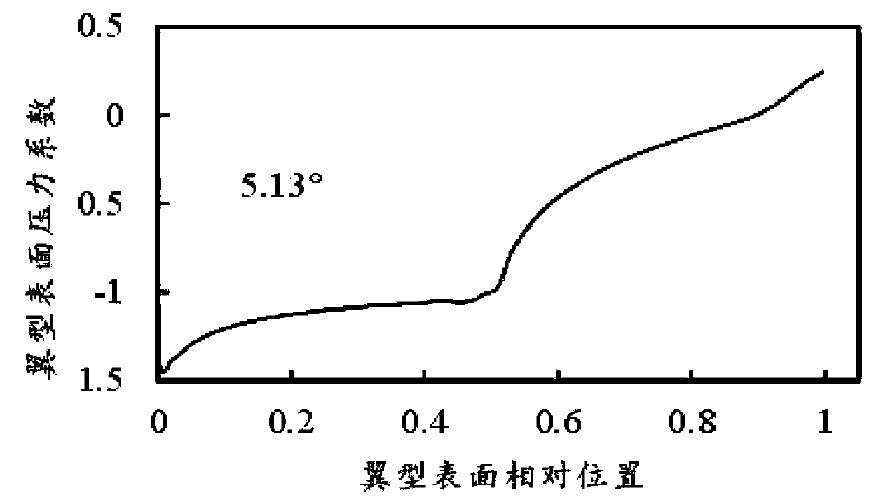
[0032] In this example, the study found that when the airfoil has a small angle of attack ( Figure 3a ) That is, when the flow separation does not occur on the surface of the wind turbine blade 1, the pressure on the upper surface will continue to increase from the middle to the trailing edge. And when the angle of attack is large ( Figure 3b ) After the flow separation occurs, the pr...


PUM


Abstract

The invention discloses an automatic telescopic vortex generator system based on a wind turbine blade. The automatic telescopic vortex generator system is characterized by comprising a fan blade, a pressure baffle plate, a homing device, a connecting rod mechanism and a vortex generator, wherein a groove is formed in the fan blade and penetrates through the blade root; the homing device is arranged in the groove in a hanging manner; an adjusting groove is formed in the side face, back to the blade root, of the homing device; a spring is mounted on the inner side of the adjusting groove in thepressure difference direction; one free end of the connecting rod mechanism is hinged to the fan blade; the other free end of the connecting rod mechanism is fixed in the part, positioned on the fan blade, of the groove through a rotary shaft; one fixed end of the connecting rod mechanism is hinged to the fan blade and is positioned between the homing device and the vortex generator; the pressurebaffle plate is connected with the connecting rod mechanism through the rotary shaft; and the pressure baffle plate stretches into the adjusting groove and is in contact with the spring. According tothe automatic telescopic vortex generator system, the connecting rod mechanism is utilized to convert the pressure difference signal at the tail edge of the blade into displacement of the vortex generator to realize automatic telescopic motion of the vortex generator and realize the effect of controlling airflow separation.

Description

technical field [0001] The invention belongs to the technical field of wind power generation, and in particular relates to an automatic retractable vortex generator system based on wind turbine blades. Background technique [0002] With the gradual increase of the installed capacity of wind turbines in my country, the size of their blades has increased significantly. However, early wind turbines mostly used thinner airfoils. Under complex and harsh operating environments, the possibility of blade breakage is very high. At present, the roots of large wind turbines generally adopt thicker airfoils to improve the structural strength of the blades, which makes the research and development of high-performance thicker airfoils necessary. The thick airfoil itself is very prone to flow separation, and the flow state of the root airfoil is often in non-design conditions, which increases the possibility of flow separation, so the flow separation is controlled to reduce the wind turbin...

Claims


Application Information

Patent Timeline
Patent Type & Authority Patents(China)
IPC IPC(8): F03D1/06
CPCF03D1/0675F05B2240/30Y02B10/30Y02E10/72
Inventor 刘青松李春缪维跑王博郝文星韩志伟许子非张立李东旭丁勤卫余万
Owner UNIV OF SHANGHAI FOR SCI & TECH
Learn More