
Automatic metal rolling formation device with cooling structure

A roll forming and cooling structure technology, applied in metal processing equipment, forming tools, manufacturing tools, etc., can solve the problems of affecting the service life of the roll, difficulty in grasping the gap between the upper and lower shafts, and difficulty in moving the shaft up and down, so as to achieve a reasonable structure setting, Strong functionality and extended lifespan

Inactive Publication Date: 2019-04-26
盐城紫环工业机械有限公司
View PDF0 Cites 0 Cited by
  • Summary
  • Abstract
  • Description
  • Claims
  • Application Information

AI Technical Summary

Problems solved by technology

[0003] 1. The double adjustment screw makes it very difficult to move the shaft up and down while keeping the upper and lower shafts parallel, and it is difficult to grasp the gap between the upper and lower shafts;
[0004] 2. When rolling metal sheets or strips, heat will be generated on the contact surface with the metal, and the heat cannot be quickly dissipated after long-term work, which will affect the service life of the rolls;
[0005] 3. When rolling some plates with a specific thickness, it needs to be adjusted in time according to the thickness of the plate, and there is no determined position that can realize the rapid positioning of the roller shaft

Method used


Image

  • Automatic metal rolling formation device with cooling structure
  • Automatic metal rolling formation device with cooling structure
  • Automatic metal rolling formation device with cooling structure

Examples


Embodiment Construction

[0022] The technical solutions in the embodiments of the present invention will be clearly and completely described below in conjunction with the accompanying drawings in the embodiments of the present invention. Obviously, the described embodiments are only a part of the embodiments of the present invention, rather than all the embodiments. Based on the embodiments of the present invention, all other embodiments obtained by those of ordinary skill in the art without creative work shall fall within the protection scope of the present invention.

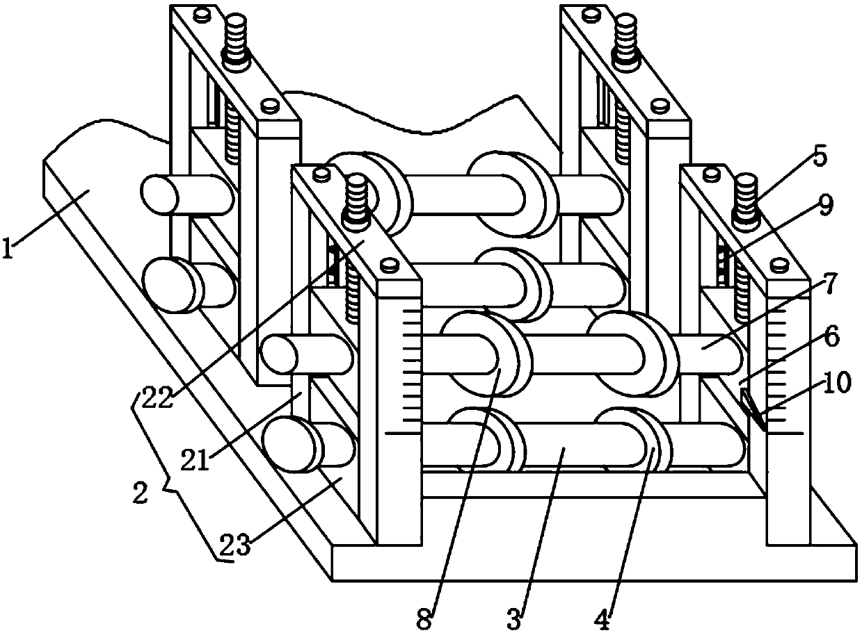
[0023] See Figure 1 to Figure 3 , The present invention provides a technical solution: an automatic roll forming equipment for metal with a cooling structure, such as figure 1 As shown, it includes a base 1 and a supporting device 2. The upper surface of the base 1 is fixedly installed with supporting devices 2 on the left and right sides. The supporting device 2 includes a vertical bracket 21, a horizontal plate 22 and a fixed block 23....


PUM


Abstract

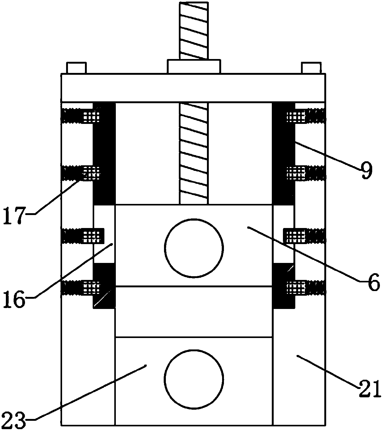
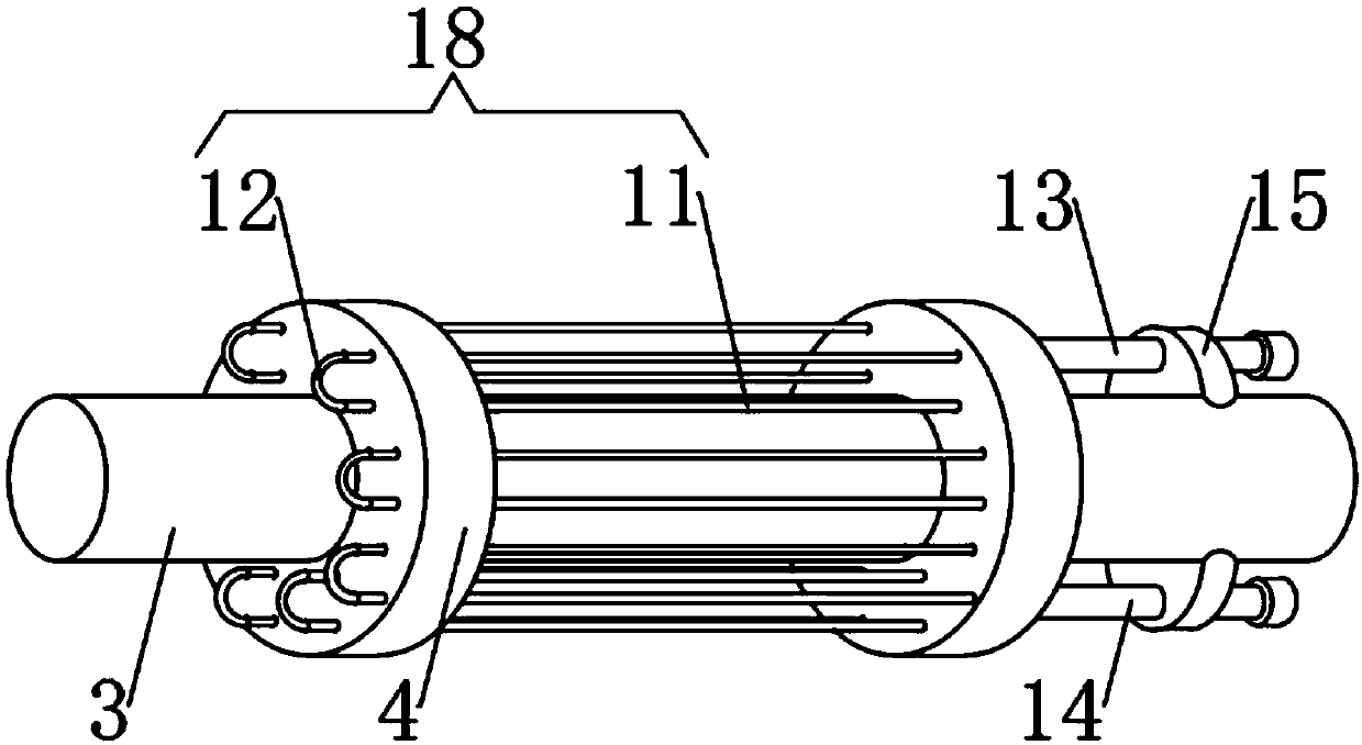
The invention discloses an automatic metal rolling formation device with a cooling structure. The automatic metal rolling formation device with the cooling structure comprises a base and a supportingdevice. The left side and the right side of the upper surface of the base are fixedly provided with supporting devices. Each supporting device comprises two vertical supports, a cross plate and fixingblocks. According to the automatic metal rolling formation with the cooling structure, through arrangement of pointers and dividing rulers, when the interval between an upper roller and a lower roller is adjusted, the distance between the rollers can be clear, and then the fixing position of a nut can be more accurately determined; since spring pins are arranged in the vertical supports, rectangular blocks can be conveniently fixed; the spring pins on different horizontal lines are corresponding to metal plates of specific thicknesses; the upper roller can be replaced by rollers of differentdiameters or in different shapes, so that plates in different shapes can be formed through rolling; a circulating water pipe is arranged between the rollers, the rolling faces can be cooled, and therefore the service life of each roller is prolonged.

Description

Technical field [0001] The invention relates to the field of mechanical equipment, in particular to an automatic roll forming equipment for metal with a cooling structure. Background technique [0002] Rolling is defined as cold roll forming in material forming. Cold roll forming is a new material-saving, energy-saving and efficient metal forming process and new technology. Cold bending is the process of arranging multiple forming rolls in sequence, and continuously playing with metal plates such as coils and strips to form profiles with specific cross-sections. In the process of roll forming, only bending deformation, except The bending angle of the blank is slightly thinned locally, and the thickness of the deformed material remains unchanged during the forming process. This processing method is particularly suitable for the processing of high-precision products with a longitudinal shape and a large batch. The existing roll forming equipment has some drawbacks when used: [000...

Claims


Application Information

Patent Timeline
Patent Type & Authority Applications(China)
IPC IPC(8): B21D5/08B21D37/16
CPCB21D5/08B21D37/16
Inventor 王宁芳
Owner 盐城紫环工业机械有限公司
Learn More