Knee joint X-ray image detection device and use method thereof
A technology of image detection and knee joints, applied in the fields of application, radiological diagnosis equipment, medical science, etc., can solve the problems of increasing the labor intensity of medical staff, the number of surgical personnel, the difficulty of treatment and detection, and the greater injury of medical staff. Achieve the effect of being convenient for X-ray image shooting, convenient for promotion and application, and excellent in adjustable performance
Pending Publication Date: 2019-04-26
XIANGYA HOSPITAL CENT SOUTH UNIV
View PDF17 Cites 3 Cited by
- Summary
- Abstract
- Description
- Claims
- Application Information
AI Technical Summary
Problems solved by technology
[0004] There are many defects in the above-mentioned method of manually maintaining the patient's surgical position: 1. Increase the labor intensity of the medical staff and the number of surgical personnel; ; 3. Medical staff are very vulnerable to X-ray radiation, which is more harmful to medical staff; 4. The force line rod cannot be placed stably directly above the legs, and there is artificial vibration, which leads to deviation from the optimal placement position, resulting
Method used
View moreImage
Smart ImageViewing Examples
Examples
 PUM
 Abstract
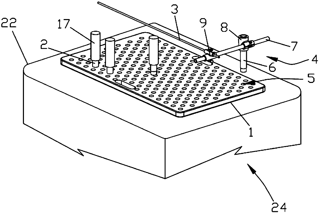
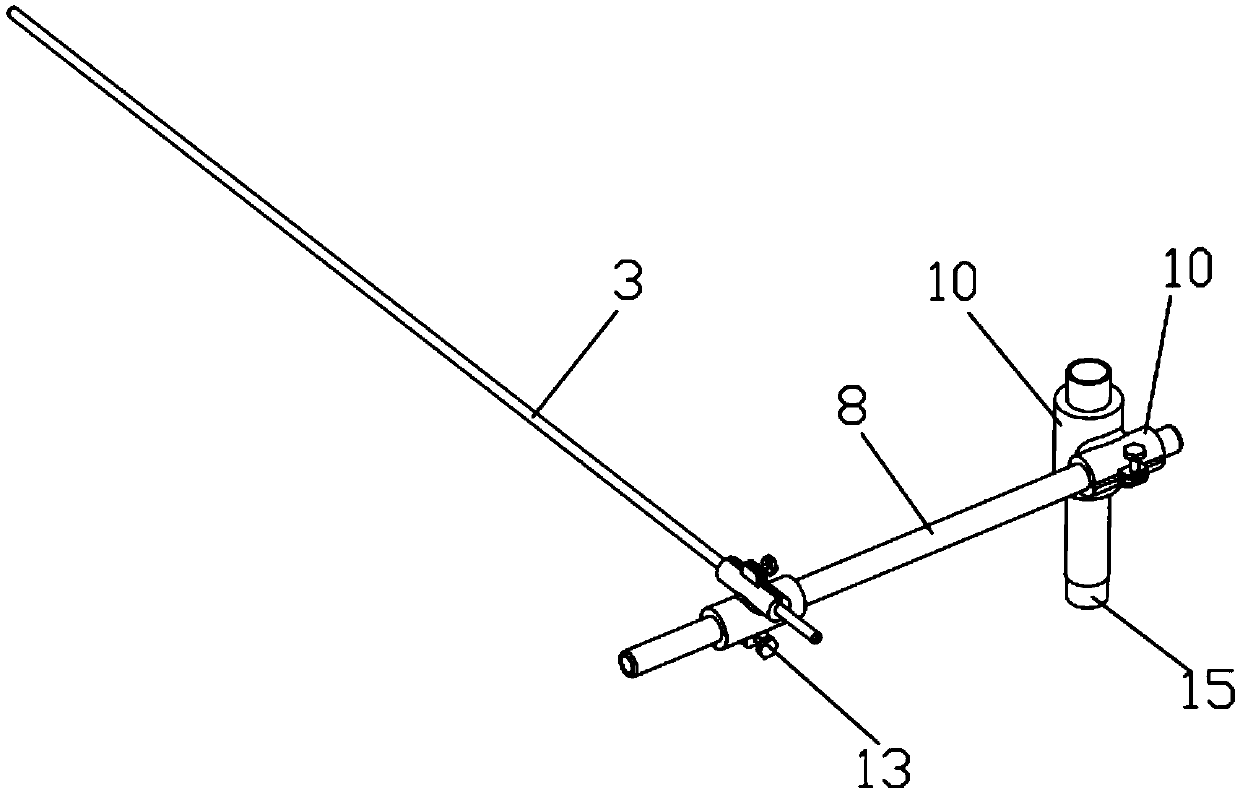
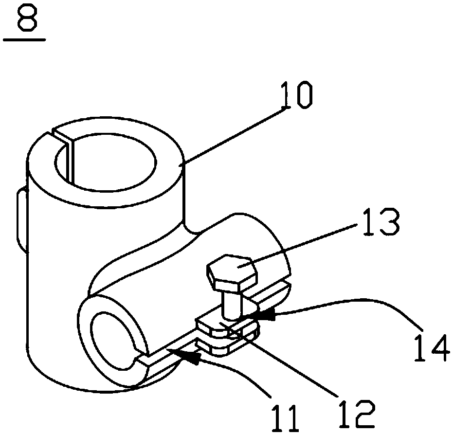
The invention discloses a knee joint X-ray image detection device and a use method thereof. The detection device comprises a bed plate, a position limiting rod, a force line rod, a force line rod fixing device and an X-ray machine, wherein the bed plate is arranged on a detection platform of the X-ray machine; insertion and connection holes in which the position limiting rods can be inserted, connected and fixed are distributed in the bed plate; the occupied width during the human body lying on the back can be at least accommodated in a space between insertion and connection holes with the longest distance in the width direction of the bed plate; the force line rod is arranged on the force line rod fixing device to extend in the length direction of the bed plate, so that when the legs of apatient are put onto the bed plate, the force line rod is suspended above the legs. On one hand, through the matching of the bed plate with the insertion and connection holes and the position limiting rod, the X-ray image shooting body position of the patient receiving knee joint operation can be precisely and stably fixed; through the force line rod fixing device, the force line rod can be precisely and stably fixed; the quantity of medical personnel during X-ray image shooting is reduced; the X-ray radiation by medical personnel is avoided.
Description
technical field [0001] The invention relates to the field of medical operation auxiliary equipment, in particular to a knee joint X-ray image detection device and a use method thereof. Background technique [0002] During the operation of the knee joint, it is often necessary to perform a stress test on the lateral orientation of the knee joint and a stress test on the front and rear drawers of the knee joint. Among them, the structural stress test in the lateral direction of the knee joint: After keeping the calf relative to the thigh in a certain deflection in the detection plane, take pictures with a C-arm X-ray machine, and at the same time use the force rod as a reference for the film after shooting Analysis, while the front and rear drawer stress test of the knee joint also needs to apply force. [0003] At present, when the C-arm X-ray machine is taking pictures, multiple medical staff need to hold the calf relative to the thigh to maintain a certain deflection on th...
Claims
Login to View More Application Information
Patent Timeline
 IPC IPC(8): A61B6/00A61B6/04
CPCA61B6/0421A61B6/505A61B2562/0247
Inventor 雷鹏飞罗振华杨序程雷庭钱湖
Owner XIANGYA HOSPITAL CENT SOUTH UNIV
Features
- R&D
- Intellectual Property
- Life Sciences
- Materials
- Tech Scout
- Unparalleled Data Quality
- Higher Quality Content
- 60% Fewer Hallucinations
Learn More Browse by: Latest US Patents, China's latest patents, Technical Efficacy Thesaurus, Application Domain, Technology Topic, Popular Technical Reports.
© 2025 PatSnap. All rights reserved.Legal|Privacy policy|Modern Slavery Act Transparency Statement|Sitemap|About US| Contact US: help@patsnap.com


