Novel self-locking nut

A self-locking nut, a new type of technology, applied in the direction of nuts, screws, bolts, etc., can solve the problem of not being fastened, and achieve the effect of reasonable structure, convenient use and simple operation

Inactive Publication Date: 2019-04-23
浙江鑫哲希科技有限公司
View PDF0 Cites 1 Cited by
  • Summary
  • Abstract
  • Description
  • Claims
  • Application Information

AI Technical Summary

Problems solved by technology

[0003] The current nuts are basically without self-locking devices, so that during the use of nuts and bolts or screws, due to the influence of vibration and other factors, the nuts and bolts or screws are separated, so that the fastening effect cannot be achieved.

Method used


Image

  • Novel self-locking nut
  • Novel self-locking nut
  • Novel self-locking nut

Examples


Embodiment 1

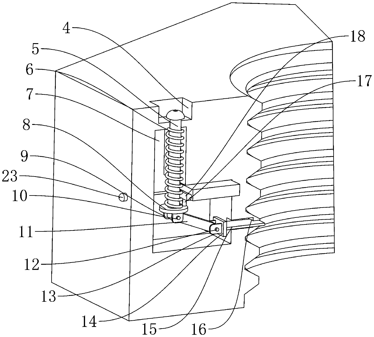
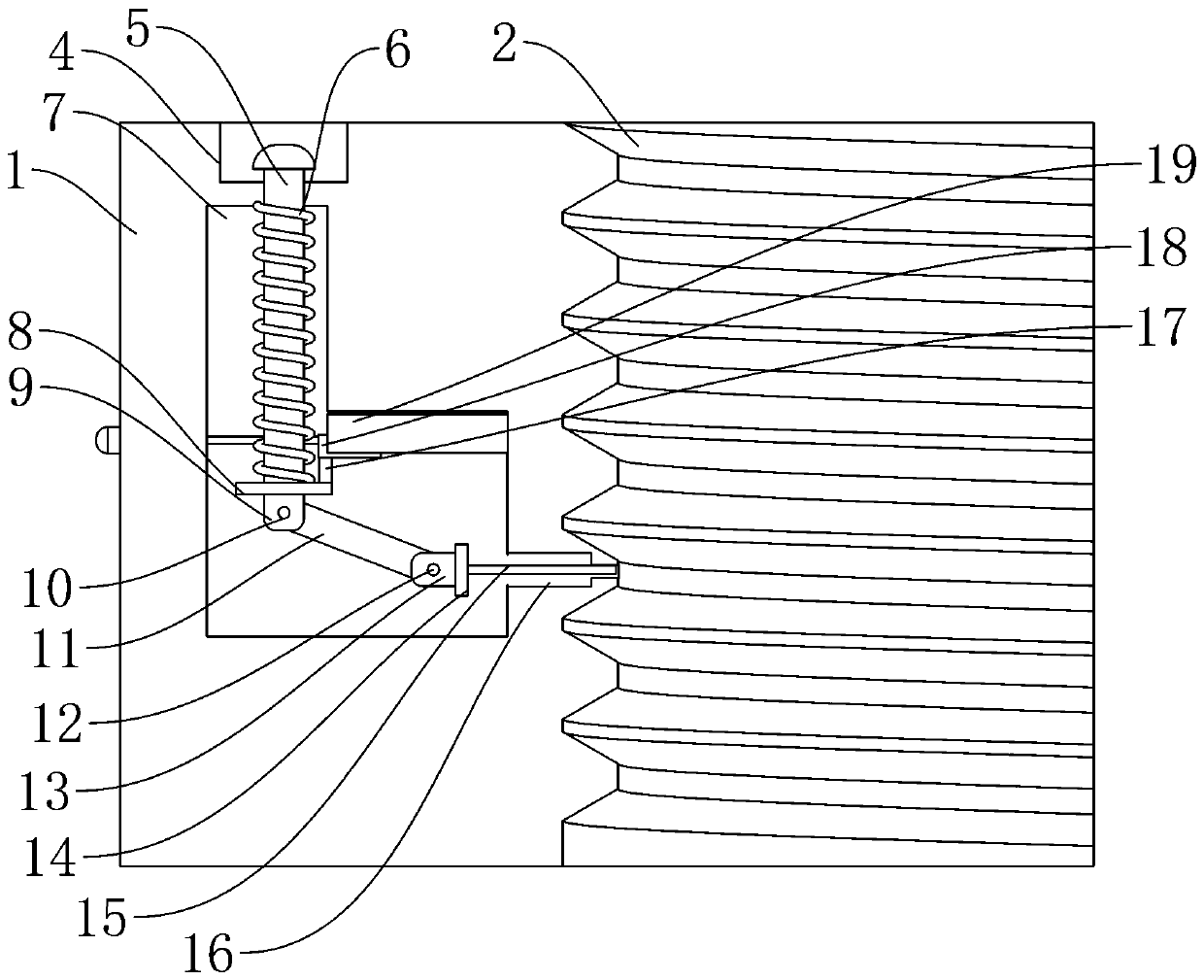
[0033] Such as Figure 1-Figure 5 As shown, a new type of self-locking nut includes a nut 1, an inner groove 7, a limit plate 15, and a stopper 19. The inner side of the nut 1 is processed with an internal thread 2, and the inner side of the nut 1 is processed with a groove 4. The function of the groove 4 is to It is convenient to operate the first connecting rod 5, the groove 4 is provided with an outer cover 3, the function of the outer cover 3 is to close the groove 4, the outer cover 3 and the nut 1 are connected by a card slot, and the inner groove 7 is arranged under the groove 4 , the function of the inner groove 7 is to install the self-locking device, the first connecting rod 5 is arranged in the inner groove 7 and the groove 4, the function of the first connecting rod 5 is to set the first mounting plate 8, and the outer side of the first connecting rod 5 is provided with a second A spring 6, the function of the first spring 6 is to reset the first connecting rod 5, ...

Embodiment 2

[0035] The difference between this embodiment and embodiment 1 is:

[0036] One side of the moving block 22 is provided with a second connecting rod 23, which is threadedly connected between the second connecting rod 23 and the moving block 22. The second connecting rod 23 communicates with the inner wall of the nut 1 and extends outside the nut 1. The second connecting rod 23 is fixed on one side of the moving block 22 , and the second connecting rod 23 can be operated outside the nut 1 .

[0037] Working principle: first fit the threaded rod into the internal thread 2, when self-locking, press the first connecting rod 5, the limit plate 15 will be pushed to the internal thread 2, and the baffle 18 will follow the first connecting rod 5 down, the second spring 21 in the block 19 pushes the moving block 22, and when the operator releases his hands, the baffle plate 18 will press the lower end of the moving block 22, thereby realizing the fixing of the position of the limiting ...


PUM


Abstract

The invention belongs to the field of self-locking nuts and particularly provides a novel self-locking nut. The novel self-locking nut comprises a nut body, an inner groove, a limiting plate and a stop block. An inner thread is machined on the inner side of the nut body. The groove is machined in the nut body. An outer cover is arranged in the groove. The outer cover and the nut body are connectedthrough a clamping groove. The inner groove is formed below the groove. First connecting rods are arranged in the inner groove and the groove. First springs are arranged on the outer sides of the first connecting rods. First installing plates are arranged at the lower ends of the first connecting rods. The first installing plates are welded to the lower ends of the first connecting rods. First connecting plates are arranged at the lower ends of the first installing plates. According to the novel self-locking nut, the stop block is utilized for fixing the ascending distance of the first connecting rods, the telescoping distance of the limiting plate can be controlled, the nut can be locked conveniently, self-locking of the nut can be completed by pressing the first connecting rods, and when the nut is screwed, unlocking of the nut can be completed by pressing second connecting rods by the way.

Description

technical field [0001] The invention belongs to the field of self-locking nuts, in particular to a novel self-locking nut. Background technique [0002] A nut is a kind of nut, which is screwed together with a bolt or a screw to act as a fastening part, and because of its shape, it is often used in occasions where the surface space of the connected parts is limited. [0003] Present nut basically all does not have self-locking device, in the process of nut and bolt or screw rod use like this, due to the influence of factors such as vibration, nut and bolt or screw rod are separated, thereby can not have the effect of fastening. Contents of the invention [0004] The object of the present invention is to provide a novel self-locking nut. [0005] The technical scheme adopted in the present invention is as follows: [0006] A new type of self-locking nut, including a nut, an inner groove, a limit plate, and a stopper. The inside of the nut is processed with an internal thr...

Claims


Application Information

Patent Timeline
Patent Type & Authority Applications(China)
IPC IPC(8): F16B39/10F16B37/00
CPCF16B39/10F16B37/00
Inventor 陈爽
Owner 浙江鑫哲希科技有限公司
Why Eureka
Try Eureka