
A multifunctional power system protection device

A power system protection and multi-functional technology, applied in the direction of cable installation device, cable installation, electrical components, etc., can solve the problems of reducing maintenance efficiency, affecting the use of power system, unable to cope with various working conditions, etc., to prevent dust pollution , the effect of easy disassembly

Inactive Publication Date: 2020-01-31
HENAN COLLEGE OF IND & INFORMATION TECH
View PDF4 Cites 0 Cited by
  • Summary
  • Abstract
  • Description
  • Claims
  • Application Information

AI Technical Summary

Problems solved by technology

[0002] There are many parts in the power system that need extra protection. Poor heat dissipation will affect the use of the entire power system. The traditional protection device has a single function and cannot cope with various working conditions. In emergency repairs, if there is no wire sheath stripping device, it is very difficult. It is easy to reduce maintenance efficiency, so this multifunctional power system protection device is designed

Method used


Image

  • A multifunctional power system protection device
  • A multifunctional power system protection device
  • A multifunctional power system protection device

Examples


specific Embodiment approach 1

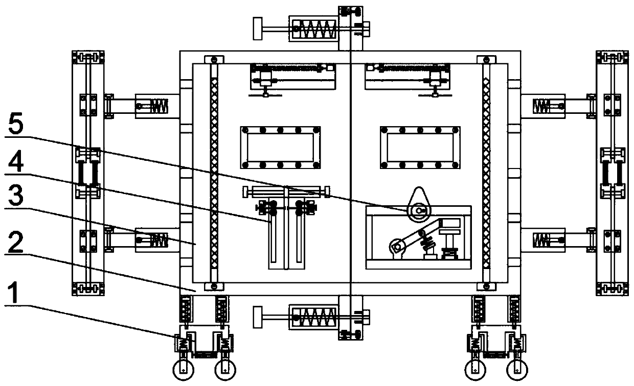
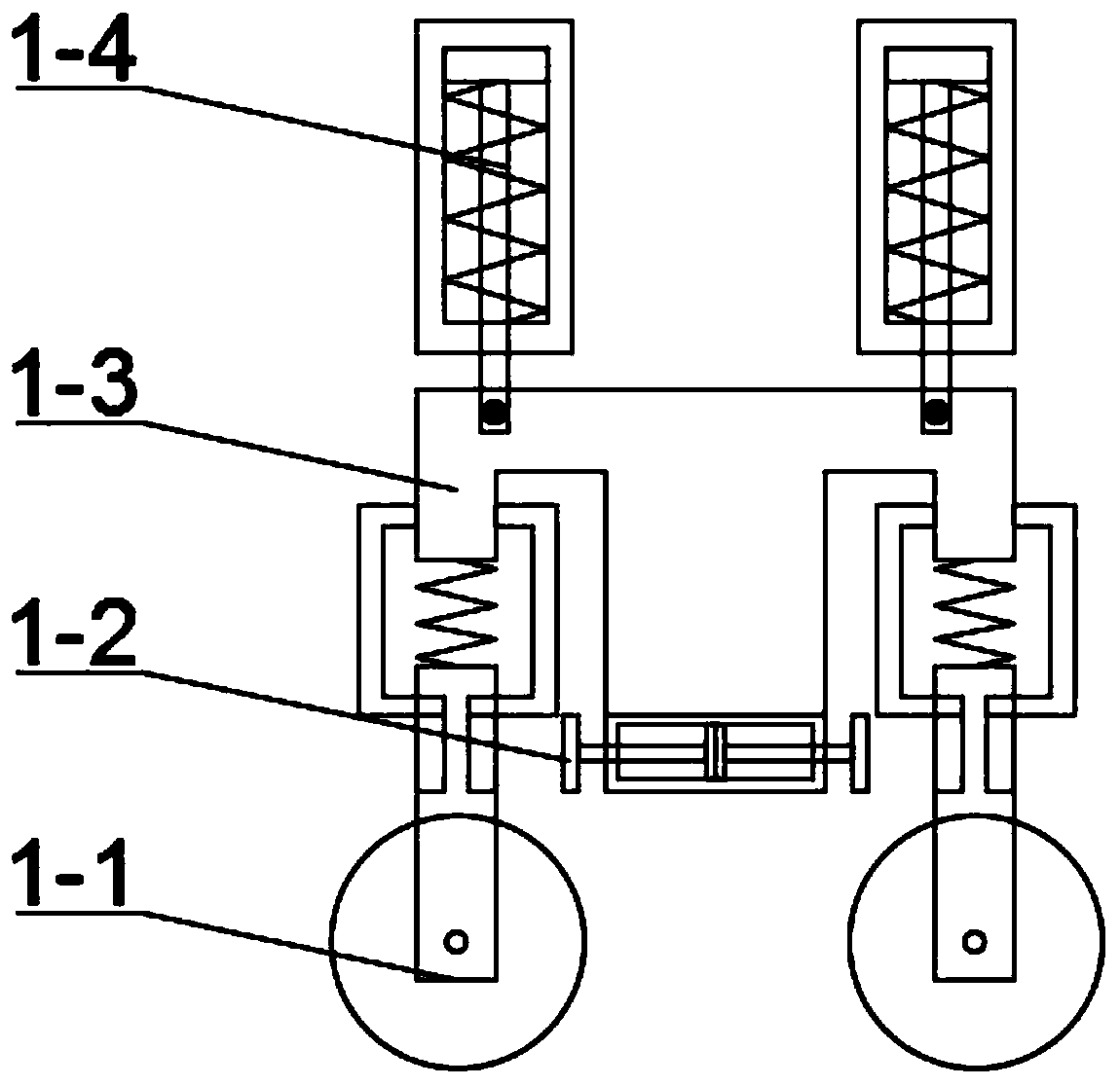
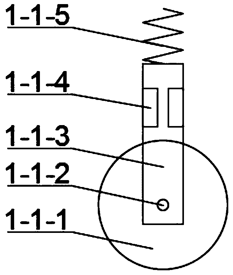
[0051] Combine below figure 1 , figure 2 , image 3 , Figure 4 , Figure 5 , Figure 6 , Figure 7 , Figure 8 , Figure 9 , Figure 10 , Figure 11 , Figure 12 , Figure 13 , Figure 14 , Figure 15 , Figure 16 , Figure 17 , Figure 18 , Figure 19 Description of this embodiment, the present invention relates to a protection device, more specifically a multi-functional power system protection device, including a multi-functional moving wheel mechanism 1, a protective shell mechanism 2, an anti-collision dust cleaning seat mechanism 3, a cable removal mechanism Leather mechanism 4, cable cutting mechanism 5, the device can switch between flat and rough roads, the device can change the height, the device can dissipate heat, the device can prevent the system from being polluted by dust, the device can clean the filter, and the device can avoid collisions , the device can be easily disassembled, the device can peel the cable, the device can cut the cable, an...

specific Embodiment approach 2

[0072] Combine below figure 1 , figure 2 , image 3 , Figure 4 , Figure 5 , Figure 6 , Figure 7 , Figure 8 , Figure 9 , Figure 10 , Figure 11 , Figure 12 , Figure 13 , Figure 14 , Figure 15 , Figure 16 , Figure 17 , Figure 18 , Figure 19 This embodiment will be described. The first embodiment will be further described in this embodiment, and the number of the multifunctional mobile wheel mechanisms 1 described above is four.

specific Embodiment approach 3

[0074] Combine below figure 1 , figure 2 , image 3 , Figure 4 , Figure 5 , Figure 6 , Figure 7 , Figure 8 , Figure 9 , Figure 10 , Figure 11 , Figure 12 , Figure 13 , Figure 14 , Figure 15 , Figure 16 , Figure 17 , Figure 18 , Figure 19 This embodiment will be described. This embodiment will further describe the first embodiment. The material of the screw 2-2-7 is 40Cr.


PUM


Abstract

The invention relates to a multifunctional power system protection device, which belongs to the field of power system protection equipment. The device can switch between flat ground and rough roads, the device can change the height, the device can dissipate heat, the device can prevent the system from being polluted by dust, and the device can Clean the filter screen, the device can prevent collision, the device can be easily disassembled, the device can peel the cable, the device can cut the cable, and the device can protect the cutting knife. The multi-functional mobile wheel mechanism is located under the protective shell mechanism. The multi-functional mobile wheel mechanism is used for the movement of the device. The protective shell mechanism is used for heat dissipation and storage of dust pollution. The anti-collision dust cleaning seat mechanism is welded on both sides of the protective shell mechanism. The connection mode between the cable peeling mechanism and the protective shell mechanism is welding, the connection mode between the cable cutting mechanism and the protective shell mechanism is welding, the anti-collision dust cleaning seat mechanism is used for dust removal, the cable peeling mechanism is used for cable peeling, and the cable cutoff Mechanism for cutting cables.

Description

technical field [0001] The invention relates to a protection device, in particular to a multifunctional power system protection device. Background technique [0002] There are many parts in the power system that need extra protection. Poor heat dissipation will affect the use of the entire power system. The traditional protection device has a single function and cannot cope with various working conditions. In emergency maintenance, if there is no wire sheath stripping device, it is very difficult It is easy to reduce the maintenance efficiency, so this multifunctional power system protection device is designed. Contents of the invention [0003] The technical problem mainly solved by the present invention is to provide a multi-functional power system protection device, the device can switch the driving mode of flat ground and rough road, the device can change the height, the device can dissipate heat, the device can prevent the system from being polluted by dust, and the d...

Claims


Application Information

Patent Timeline
Patent Type & Authority Patents(China)
IPC IPC(8): H02G1/12H02G1/00
CPCH02G1/005H02G1/1256
Inventor 焦贺彬李涛涛
Owner HENAN COLLEGE OF IND & INFORMATION TECH
Learn More