
Fingerprint acquisition method and related product

A fingerprint collection and fingerprint technology, which is applied to instruments, character and pattern recognition, computer parts, etc., can solve the problems of reducing the quality of fingerprint image collection, dry fingers, and unclear fingerprint images, so as to improve the quality of fingerprint image collection and improve the quality of fingerprint images. Contrast, clear image effect

Active Publication Date: 2019-04-19
GUANGDONG OPPO MOBILE TELECOMM CORP LTD
View PDF3 Cites 7 Cited by
  • Summary
  • Abstract
  • Description
  • Claims
  • Application Information

AI Technical Summary

Problems solved by technology

[0003] Fingerprint identification technology has also become a standard technology for electronic equipment. With the development of fingerprint identification technology, the optical fingerprint identification module is currently more popular. The optical fingerprint identification module can be well integrated under the screen. Its main working principle Yes: Use the display itself to emit light. When the finger is placed on the screen, the self-luminescence will be reflected when it reaches the finger. The optical fingerprint recognition module receives the reflected light signal. Due to the uneven texture of the fingerprint, the light absorption range is different, thus obtaining Fingerprint images with different light and dark, however, under low temperature conditions, the user's fingers will appear dry fingers, due to shallow and dry lines, resulting in unclear fingerprint images collected, thus reducing the quality of fingerprint image collection

Method used


Image

  • Fingerprint acquisition method and related product
  • Fingerprint acquisition method and related product
  • Fingerprint acquisition method and related product

Examples


Embodiment Construction

[0029] In order to enable those skilled in the art to better understand the solution of the present application, the technical solution in the embodiment of the application will be clearly and completely described below in conjunction with the accompanying drawings in the embodiment of the application. Obviously, the described embodiment is only It is a part of the embodiments of this application, not all of them. Based on the embodiments in this application, all other embodiments obtained by persons of ordinary skill in the art without creative efforts fall within the protection scope of this application.

[0030] The terms "first", "second" and the like in the specification and claims of the present application and the above drawings are used to distinguish different objects, rather than to describe a specific order. Furthermore, the terms "include" and "have", as well as any variations thereof, are intended to cover a non-exclusive inclusion. For example, a process, method...


PUM


Abstract

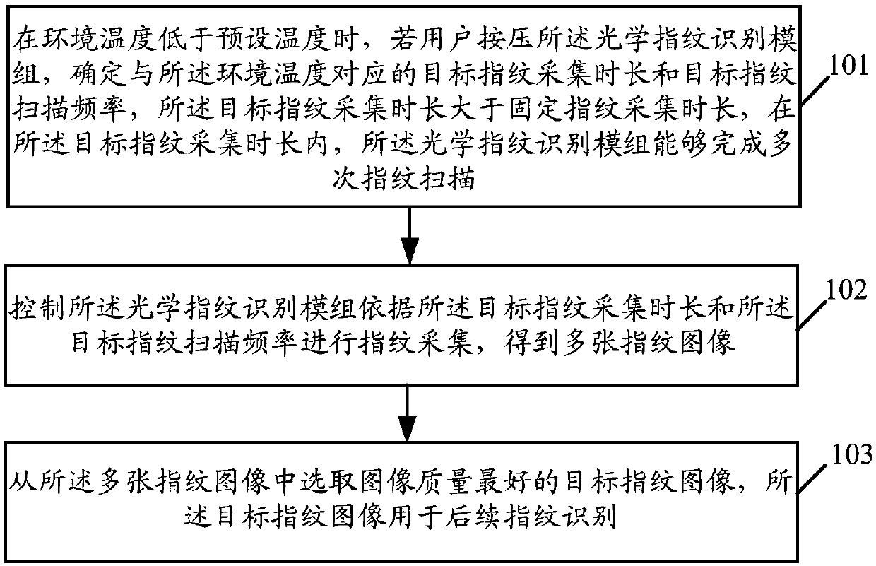
The embodiment of the invention discloses a fingerprint acquisition method and a related product. Application to electronic equipment, The electronic device comprises an optical fingerprint identification module. The method comprises the following steps of: obtaining a target object; when the environment temperature is lower than the preset temperature, if a user presses the optical fingerprint recognition module, the target fingerprint collection time length and the target fingerprint scanning frequency corresponding to the environment temperature are determined, the target fingerprint collection time length is larger than the fixed fingerprint collection time length, and within the target fingerprint collection time length, the optical fingerprint recognition module can complete multipletimes of fingerprint scanning; Controlling the optical fingerprint identification module to perform fingerprint acquisition according to the target fingerprint acquisition duration and the target fingerprint scanning frequency to obtain a plurality of fingerprint images; And selecting a target fingerprint image with the best image quality from the plurality of fingerprint images, wherein the target fingerprint image is used for subsequent fingerprint identification. According to the embodiment of the invention, the fingerprint image acquisition quality can be improved.

Description

technical field [0001] This application relates to the technical field of electronic equipment, in particular to a fingerprint collection method and related products. Background technique [0002] With the popularization and application of electronic devices (such as mobile phones, tablet computers, etc.), electronic devices can support more and more applications, and their functions are becoming more and more powerful. Indispensable electronic supplies. [0003] Fingerprint identification technology has also become a standard technology for electronic equipment. With the development of fingerprint identification technology, the optical fingerprint identification module is currently more popular. The optical fingerprint identification module can be well integrated under the screen. Its main working principle Yes: Use the display itself to emit light. When the finger is placed on the screen, the self-luminescence will be reflected when it reaches the finger. The optical fing...

Claims


Application Information

Patent Timeline
Patent Type & Authority Applications(China)
IPC IPC(8): G06K9/00
CPCG06V40/1324G06V40/1347Y02D30/70
Inventor 袁石林
Owner GUANGDONG OPPO MOBILE TELECOMM CORP LTD
Learn More