
Movement support arm moment balancing device

A technology of balance device and arm strength, applied in the field of torque control, which can solve problems such as unstable load, increased system weight, and large motor torque, and achieve the effects of preventing deformation in other directions, high environmental adaptability, and easy replacement

Pending Publication Date: 2019-04-19
NO 27 RES INST CHINA ELECTRONICS TECH GRP
View PDF0 Cites 0 Cited by
  • Summary
  • Abstract
  • Description
  • Claims
  • Application Information

AI Technical Summary

Problems solved by technology

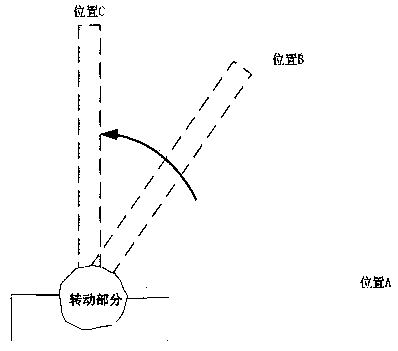
[0002] At present, in the control system of the moving arm, such as figure 1 In the moving support arm system shown, if you want to raise the load from position A to position B, and then to position C, in the process of using a common crane, the load moment changes moment by moment, and it is a nonlinear The nonlinear change of the load torque will greatly increase the burden on the power output components, requiring the motor to have a larger output torque and a faster torque change speed, which increases the instability of the entire control system and will also cause load unstable
[0003] In order to overcome this nonlinear variable torque, a solution is to install the corresponding counterweight in the opposite direction of the load. Although this method can solve a certain variable torque, it not only increases the weight of the entire system, but also increases the load. The movement radius of the moving support arm is increased; another solution is to use a large-torque motor, relying on the powerful output torque of the motor to overcome this nonlinear variable torque, which requires the motor not only to have a large torque but also to have a short torque adjustment time. For the motor The requirements are relatively high, and while this method solves the problem, the hardware cost is greatly increased; the last method is to install a torque balancing machine, but most of the existing torque balancing machines are linear, not only large in size, but also compatible with The adaptability of the load moment change is low, it is easy to increase the burden of the control system, and it cannot solve the above problems well

Method used


Image

  • Movement support arm moment balancing device
  • Movement support arm moment balancing device
  • Movement support arm moment balancing device

Examples


Embodiment Construction

[0018] The following will clearly and completely describe the technical solutions in the embodiments of the present invention with reference to the drawings in the embodiments of the present invention. Based on the embodiments of the present invention, all other embodiments obtained by persons of ordinary skill in the art without making creative efforts belong to the protection scope of the present invention.

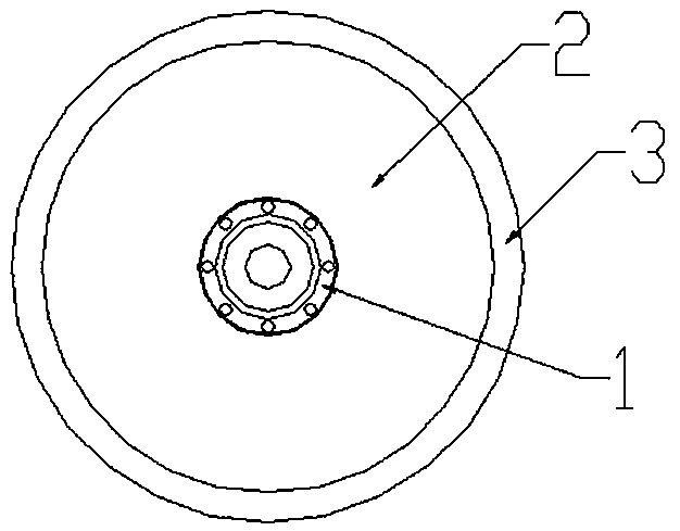
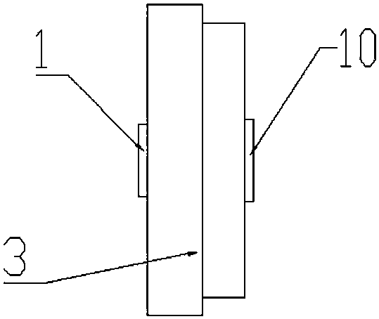
[0019] Such as figure 1 , 2 , 3, 4 and 5, the shell of the present invention and the output flange 1 and the input flange 10 arranged on the shell; the shell is formed by covering the side cover plate 2 and the shell bottom 3 with a concave cavity; A transmission mechanism is also provided in the cavity, the transmission mechanism includes a planet carrier 4, a spring 5, a spring guide groove 6, a planetary gear 7, a sun gear 8, an external gear 9 and a bearing 11, and the input flange 10 is fixed At one end of the inner ring of the bearing 11, the sun gear 8 is fixe...


PUM


Abstract

The invention discloses a movement support arm moment balancing device. The movement support arm moment balancing device comprises a shell, an output flange and an input flange, wherein the output flange and the input flange are arranged on the shell; the shell is formed by closing a side cover plate and a shell bottom with a cavity; and a transmission mechanism is also arranged in the cavity andcomprises a planet carrier, a spring, a spring guide groove, and a bearing. Equipment such as a motor and an angle encoder can be conveniently installed through the concise flange design; a circular moment balancing device with a spring mechanism can realize the balancing of arbitrary angles and loading moment through the spring design; a sun wheel planetary gear train is further adopted for reducing the expansion and contraction quantity of a spring, thereby allowing the loading wide-angle movement; and the guide groove is formed in the spring to prevent the spring from deforming in other directions and cause the spring to be easily replaced. The movement support arm moment balancing device can accurately balance the movement support arm moment and has relatively high environmental adaptability.

Description

technical field [0001] The invention relates to the technical field of moment control, in particular to a moment balance device for a moving support arm. Background technique [0002] At present, in the control system of the moving arm, such as figure 1 In the moving support arm system shown, if you want to raise the load from position A to position B, and then to position C, in the process of using a common crane, the load moment changes moment by moment, and it is a nonlinear The nonlinear change of the load torque will greatly increase the burden on the power output components, requiring the motor to have a larger output torque and a faster torque change speed, which increases the instability of the entire control system and will also cause load unstable. [0003] In order to overcome this nonlinear variable torque, a solution is to install the corresponding counterweight in the opposite direction of the load. Although this method can solve a certain variable torque, i...

Claims


Application Information

Patent Timeline
IPC IPC(8): F16H1/32F16H57/00
CPCF16H1/32F16H57/0025
Inventor 杨国文姚红萍夏旭光李红卫
Owner NO 27 RES INST CHINA ELECTRONICS TECH GRP
Learn More